A320 EFIS CONTROL PANEL
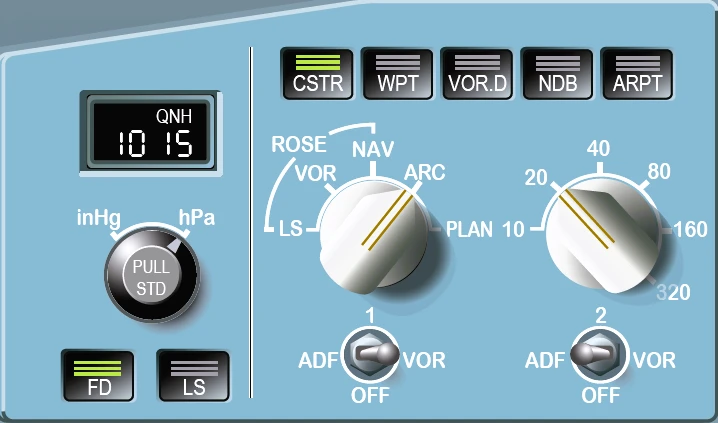
Barometer Reference Display Window
Range : 745 hPa to 1100 hPa.
Barometer Reference Selector
- Outer ring : For selection of the units for the barometer reference-either, hectoPascals (HPA) or inches of mercury (in Hg). Note: The unit selected does not appear on the PFD.
- Inner knob : For selection of the reference value displayed in the barometer reference display window and on the PFD below the altitude scale. At FCU initialization, the window displays 1013 or 29.92, depending on the unit selected.
- The flight crew turns the barometric reference knob to select the QNH value.
- The flight crew pulls or pushes the barometric reference knob to select the barometric reference (QNH or STD).
- When the flight crew pulls the barometric reference knob, the barometric reference value is set to STD.
- When the flight crew pushes the barometric reference knob, the barometric reference is set to QNH.
- The selected QNH value appears in the barometric reference window, and under the altitude scale on the PFD.
- At the EFIS CP power-up, the barometric reference is QNH and the QNH value is set to 1013 hPa or 29.92 inHg, depending on the selected barometric unit.
FD Pushbutton
- Pushing this button removes the FD bars from the associated PFD (or removes the flight path director symbol if the TRK FPA reference is selected). The pushbutton light goes out.
- Pushing it again restores the FD bars (or the FPD symbol) and the green pushbutton light comes on.
LS Pushbutton
- Pushing this button displays the localizer and glide slope scales on the PFD.
- Deviation symbols appear if there is a valid ILS signal.
- The green pushbutton light comes on.
Mode Select Switch
- This switch selects a navigation display for the onside ND.
- If the flight crew selects the PLAN mode, the ND does not display terrain, weather, or traffic information.
Range Select Switch
- This switch selects a range scale for the onside ND.
- Note: If the mode or the range data fails, the default selection is the ROSE NAV mode and 80 nm range.
ADF-VOR Select Switches
- These switches select ADF or VOR bearing pointers and DME distance on the onside ND, as well as the corresponding NAVAID data characteristics in any mode except PLAN mode.
Optional Data Display Pushbutton
- Pushing this button displays optional data in addition to the data permanently displayed in PLAN, ARC, or ROSE NAV modes.
- The green pushbutton light comes on.
- Only one option can be activated at a time.