The Aircraft Electrical System makes, supplies, and controls electrical power to aircraft. The complete system can be considered to be made up of different equipment circuits and power supply circuits.
The aircraft electrical system has automatic and manual control features. The system also has protection features.
The electrical system makes and supplies AC and DC power to the aircraft. A standby AC and DC system give normal and emergency power.
Built-in test equipment (BITE) and alternate source selection make the electrical power reliable and easy to keep.
Before going deep inside the aircraft electrical system, let’s clear some basics of electricity.
Basics of Electricity
- Voltage – Voltage is electrical pressure and it’s measured in terms of volts. Its symbol is “V” or “E”.
- Current – Current is the movements of electrons and it’s measured in amps and expressed as “A” or “I” in drawings.
- Resistance – Resistance is the opposition offered to current flow. It is measured in Ohms (Ω), and its symbol is “R” or “Ω”.
- Power – Power is the rate of doing work. It is measured in Watts and expressed as “W” or “P”.
Conventional flows of current are from +ve to -ve. The current will not flow unless there is a complete circuit and there is a voltage (pressure) to drive electrons.
Basics of Aircraft Electrical System
The complete electrical system of aircraft is made of supply and consumer circuits. Consumer circuits are also known as equipment circuits.
Each equipment circuit provides electricity to various components. They all take their supplies from bus bars that are supplied by generators and /or batteries.
Power supply circuits include generator circuits and battery circuits with transformers and rectifiers. They supply electricity to the bus bars.
Generators can be driven by the aircraft engines; by a Ram Air Turbine (RAT); by a hydraulically driven motor and by the APU (Auxiliary Power Unit).
The normal source of supply is by generators driven by the aircraft engines.
Components of Aircraft Electrical System
- Generators
- Batteries
- Bus-bars
- Transformer Rectifiers
- Inverters
- Switches
- Micro-switches
- Proximity switches
- Circuit breakers
- Relays and Contactors
- Fuses
- Motors
1. Generator
A generator is a machine that converts mechanical energy into electrical energy by the process of electromagnetic induction.
There are two types of the generator – AC generator, and DC generator. In both AC and DC types of generator, the voltage induced is alternating. The major difference between both generators being in the method by which the electrical energy is collected and applied to the circuit externally connected to the generator.
2. Battery
A battery is a device made up of a number of cells that depend on battery utilization. The cells convert chemical energy into electrical energy.
A battery may be of the primary cell type or secondary cell type.
Both types of cells exchange the electrons due to the chemical action of an electrolyte and electrode materials.
The difference between the two cells is in the action that occurs during discharge.
Primary cells destroy the active materials of the cell, however secondary cells convert the active material into from which they can subsequently be electrically reconverted into the original materials. The action of re-conversion is more commonly known as charging.
The batteries selected for use in aircraft, therefore, employ secondary cells and are either of the lead-acid or nickel-cadmium types.
3. Bus-Bar
The output from generators and batteries is supplied to bus-bars. Then all electrical services take their supplies from the bus-bars.
Aircraft electrical services can be split into the following groups:
Vital Services – Services would be required after an emergency. Components take their supply from the “hot” battery bus or vital battery bus. The emergency lights are also powered from this bus with their own battery back-up.
Essential Services – Services required to ensure a safe landing in an in-flight emergency. The bus-bars are connected in such a way that they can be fed from a generator or battery. Usually called a DC essential bus and an AC essential bus.
Non-essential Services – Services that can be isolated in an in-flight situation eg, galley supplies, in-flight entertainment, etc. They can also be subject to load shedding. The actual name may vary but there will be a non-essential ac bus and a non-essential dc bus.
4. Transformer Rectifiers
These are often used to charge batteries from AC generators.
Rectifiers – Rectifiers convert AC into DC. The process of converting an ac supply to a dc supply is known as rectification.
Transformer – Transformers are electrical components that transfer electrical energy from one circuit to another through inductively coupled electrical conductors. This only works with AC. It has two coils. The primary coil is supplied with ac. This ac supply causes it to produce an alternating magnetic flux field. This alternating flux field cuts back and forth across the secondary coil and induces an ac voltage into it. If the secondary coil has fewer windings than the primary then the voltage is reduced – if it has more windings then the voltage is increased.
5. Inverters
These convert dc to ac and may be rotary or static. A rotary inverter employs a dc motor driving an ac generator and a static inverter employs a solid-state square wave generator. Rotary inverters are very inefficient.
6. Switches
A switch is used to isolate the circuits. Some other switch types are used to direct the current into pre-determined parts of a circuit. Switches are characterized by the number of poles, number of switched positions, and type of switched contacts (permanent or momentary).
7. Micro-switches
Micro-switches are used to sense if a device has moved or has reached its limit of travel. They are attached to the structure and the wiring is connected to a control circuit. Micro-switches are usually pushbutton switches.
8. Proximity switches
Proximity switches used in similar locations to micro-switches like cargo doors, passenger doors, and landing gear UP and DOWN locks.
9. Relays and Contactors
A relay is simply an electro-mechanical switch where a small amount of current can control a large amount of current.
Relays and Contactors are almost the same things. Both operate in the same way. The difference between them is their physical construction and application.
Relays are generally used for low current applications. Contactors are also known as breakers. Contactors are used for switching higher currents. For example, the Contactor can be used for connecting battery power to the aircraft. The features of a contactor include the main power contacts and auxiliary contacts used for indication and control of other devices.
10. Circuit Breaker
The circuit breaker is commonly used in place of a fuse. It is designed to break the circuit and stop the current flow when the current exceeds a predetermined value. Unlike the fuse, the circuit breaker can be reset; whereas the fuse or current limiter must be replaced.
11. Fuses
Fuses are protective devices designed to interrupt an electric circuit whenever the current reaches a level that could cause damage to the wiring or components within the circuit. The fuse is a “weak link” in a circuit. It is placed in series with the load so that all load current will flow through it. When the current flowing through a fuse exceeds the minimum fusing value, the element melts and breaks the circuit, and current flow ceases.
12. Motors
Electric motors are devices that changes electric power to mechanical energy. A coil of wire through which the current flows rotates when placed in a magnetic field.
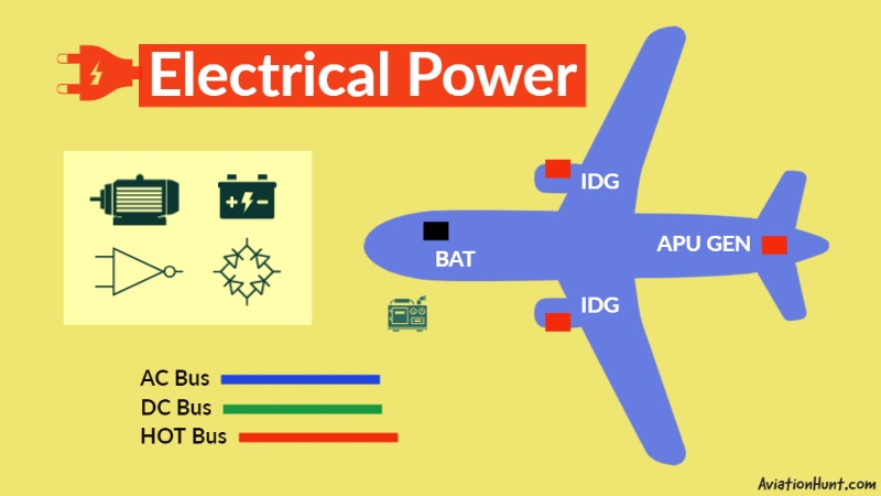
A320 Aircraft Electrical System
Electrical Power System consists of a three-phase 115/200V, 400Hz constant-frequency AC system, and a 28V DC system.
AC System – AC generation
The two engine generators provide the AC main generation. The AC main generation supplies the whole aircraft in normal flight configuration. Two Integrated Drive Generators (IDG) normally supply the aircraft electrical power in flight. Each engine drives one generator. The whole AC system includes 2 IDG, 1 APU GEN, 1 EMR GEN, 1 STATIC INVERTER, and EXT PWR receptacle.
ENGINE DRIVEN GENERATORS
- GEN 1 – IDG 1 – ENG 1 (115/200 volts, three-phase, 400 Hz, 90 KVA)
- GEN 2 – IDG 2 – ENG 2 (115/200 volts, three-phase, 400 Hz, 90 KVA)
- Each IDG is controlled and monitored by its own Generator Control Unit (GCU). GEN 1 – GCU 1, GEN 2 – GCU 2.
APU GENERATOR AND EXTERNAL POWER
The APU drives a third, auxiliary, generator called APU GEN. APU Generator can replace one or both main engine generators throughout the flight envelope. This also supplies the aircraft electrical network when the electrical ground power unit is not available. The aircraft network can be supplied by a ground power unit. For this, an external power receptacle is provided.
- APU GEN – 115/200 volts, three-phase, 400 Hz, 90 KVA
- EXT PWR – 115/200 volts, three-phase, 400 Hz, 90 KVA
- A Ground and Auxiliary Power Unit (GAPCU) controls both the APU generator and the EXT PWR.
EMERGENCY GENERATOR
The AC emergency generation enables part of the distribution network to be recovered in case of loss of the two main generation sources and unavailability of the auxiliary generation. The blue hydraulic circuit drives an emergency generator that automatically supplies emergency AC power to the aircraft electrical system, if all main generators fail.
- EMER GEN – RAT Hydraulic Circuit (115/200 volts, three-phase, 400 Hz, 5 KVA)
STATIC INVERTER
A static inverter transforms DC power from Battery 1 into one KVA of single-phase 115 V 400 Hz AC power, which is then supplied to part of the AC essential bus.
- STAT INV – DC Power from Battery 1 – AC (115 volts, single phase, 400 Hz, 1 KVA)
DC System – DC generation
The aircraft DC power generation is provided by three Transformers Rectifiers (TR). The DC system includes 3 transformer rectifiers and 2 batteries.
TRANSFORMER RECTIFIERS (TRS)
Two main transformer rectifiers, TR 1 and TR 2 supply the aircraft’s electrical system, with up to 200 A of DC current. A third (identical) transformer rectifier, the ESS TR, can power the essential DC circuit from the emergency generator, if the engine and APU generators all fail, or if TR 1 or TR 2 fails. Each TR controls its contactor by the internal logic.
- TR1 – GEN 1
- TR2 – GEN 2
- ESS TR – EMER GEN
BATTERIES
Two main batteries, each with a normal capacity of 23 Ah with a nominal voltage of 24V, are permanently connected to the two hot buses. Each battery has an associated Battery Charge Limiter (BCL). The BCL monitors battery charging and controls its battery contactor.
- BAT 1 – BCL 1
- BAT 2 – BCL 2