An aircraft turn is a maneuver where the aircraft changes direction by banking its wings (tilting) and using control surfaces to counteract opposing forces. It involves balancing centripetal force pulling the aircraft inwards with lift force generated by the wings at an adjusted angle of attack.
An aircraft uses different mechanisms to turn in the air and on the ground. In the air, aircraft turn by rolling, which involves changing the lift on the wings using the ailerons and rudder. On the ground, aircraft turn by steering the nose wheel and adjusting the braking and thrust on the main wheels.
In this article, we will learn how an aircraft turns in the air. We will explore the principles of aerodynamics that govern the turning of aircraft during flight.
Forces Acting on an Aircraft
An aircraft in flight is constantly in the grip of four forces: lift, weight, thrust, and drag.
- Lift: Lift is the upward force that opposes the weight of the airplane and supports it in the air. Lift is generated by the flow of air over the wings of the aircraft.
- Weight: Weight is the force exerted by gravity on the aircraft downwards towards the center of the Earth. It opposes lift and tries to pull the aircraft down.
- Thrust: Thrust is the forward force that propels the aircraft through the air. It opposes drag and is generated by the aircraft’s engines.
- Drag: Drag is the resistance encountered by the aircraft as it moves through the air. It opposes thrust and is caused by the disruption of the air around the aircraft.
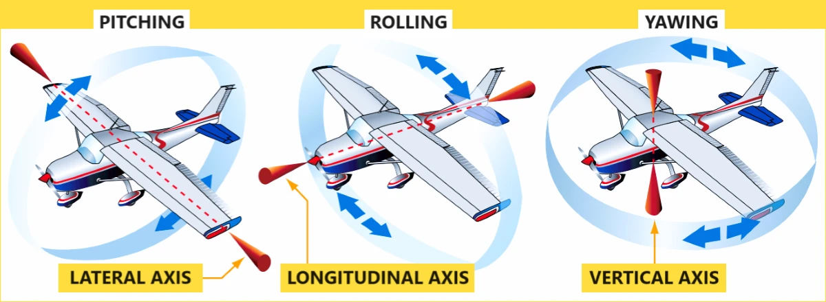
Three Axes of Rotation
An aircraft moves in three dimensions and therefore rotates along three axes:
- Pitch: The pitch axis is horizontal and perpendicular to the aircraft. When an aircraft pitches, its nose moves up or down.
- Roll: The roll axis is longitudinal, running from the nose to the tail of the aircraft. When an aircraft rolls, it tilts its wings up or down.
- Yaw: The yaw axis is vertical, running from the top to the bottom of the aircraft. When an aircraft yaws, its nose moves left or right.
Control Surfaces of an Aircraft
The aircraft’s control surfaces are movable parts that allow the pilot to adjust the aircraft’s attitude and direction of flight. They include:
- Ailerons: Located on the trailing edge of the wings, ailerons control roll. When the pilot moves the control stick left or right, the ailerons move in opposite directions, causing the aircraft to roll.
- Rudder: Located on the trailing edge of the vertical stabilizer, the rudder controls yaw. When the pilot presses the rudder pedals, the rudder moves left or right, causing the aircraft to yaw in the corresponding direction.
- Elevators: Located on the trailing edge of the horizontal stabilizer, elevators control pitch. When the pilot moves the control stick forward or backward, the elevators move up or down, causing the aircraft to pitch down or up, respectively.
Overcoming Inertia – To turn an Aircraft
Newton’s first law tells us that an object remains in motion unless acted upon by an external force. To turn an aircraft, pilots must overcome inertia. This is achieved by using ailerons to create a turning force, which alters the lift vector and introduces a horizontal component, leading to a bank.
Primary Forces During Turn
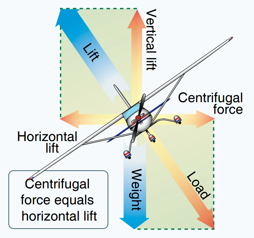
- Lift in a Bank: When an aircraft banks, the lift does not act directly opposite to the weight. Instead, it acts in the direction of the bank. This means that lift acts inward toward the center of the turn, as well as upward.
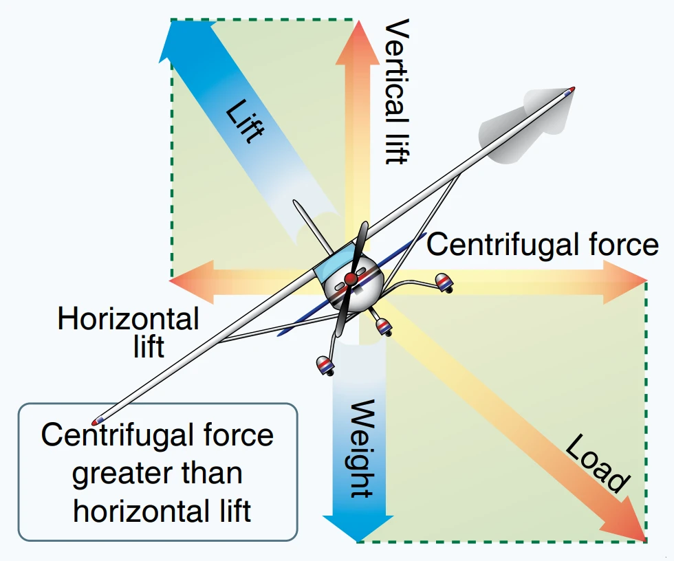
- Components of Lift: During a turn, the force of lift is separated into two components at right angles to each other. One component called the “vertical component of lift,” acts vertically and opposite to the weight (gravity). The other component, called the “horizontal component of lift” or centripetal force, acts horizontally toward the center of the turn. This horizontal component of lift is the force that pulls the aircraft from a straight flight path to make it turn.
- Centrifugal Force: Centrifugal force is the “equal and opposite reaction” of the aircraft to the change in direction. It acts equal and opposite to the horizontal component of lift.
How an Aircraft Turns
An aircraft turns by banking, or rolling, to one side. This is achieved by changing the lift generated by each wing. The wing on the inside of the turn generates less lift, and the wing on the outside generates more lift, causing the aircraft to roll.
Once the aircraft is banked, the lift is no longer acting straight up but instead has a horizontal component. This horizontal component of lift is what causes the aircraft to change direction and turn. The steeper the bank, the larger the horizontal component of lift, and the tighter the turn.
Role of Ailerons in Initiating a Turn
The ailerons, located on the trailing edge of each wing, are the primary control surfaces used to initiate a turn. When the pilot moves the control stick to the left or right, the ailerons move in opposite directions. The aileron on the wing on the outside of the turn moves down, increasing the lift generated by that wing. The aileron on the wing on the inside of the turn moves up, decreasing the lift generated by that wing. This difference in lift causes the aircraft to roll, or bank, and the turn begins.
Role of Rudder in Balancing the Turn
The rudder, located on the trailing edge of the vertical stabilizer, plays a crucial role in balancing the turn and preventing adverse yaw. Adverse yaw is a tendency for the aircraft to yaw, or twist, in the opposite direction of the turn. This is caused by the increased drag from the down-going aileron on the outside wing.
To counteract adverse yaw, the pilot applies the rudder in the same direction as the turn. This causes the aircraft to yaw slightly in the direction of the turn, aligning the aircraft with its path through the air and balancing the turn.
In a correctly executed turn, the force that turns the aircraft is not supplied by the rudder. The rudder is used to correct any deviation between the straight track of the nose and tail of the aircraft into the relative wind. If no rudder is used in a turn, the nose of the aircraft yaws to the outside of the turn. The rudder is used rolling into the turn to bring the nose back in line with the relative wind. Once in the turn, the rudder should not be needed.
Role of Elevators in Controlling the Pitch During a Turn
The elevators, located on the trailing edge of the horizontal stabilizer, control the pitch of the aircraft, or its up and down movement. During a turn, the lift is divided between maintaining altitude and turning the aircraft. This means there is less lift available to oppose weight, and the aircraft tends to descend.
To maintain altitude during a turn, the pilot pulls back on the control stick, causing the elevators to move up. This increases the angle of attack and the lift generated by the wings, allowing the aircraft to maintain altitude during the turn.
Impact of Adverse Yaw
Adverse yaw has a negative impact on turning an aircraft.
Adverse yaw is a phenomenon that occurs when an airplane turns. It’s the tendency for the airplane to yaw in the opposite direction of the turn.
Here’s how it works:
When you roll your airplane to initiate a turn, the aileron on the wing inside the turn (the down-going wing) goes up, and the aileron on the wing outside the turn (the up-going wing) goes down. The aileron that goes up creates less lift and less drag, while the aileron that goes down creates more lift and more drag. This difference in drag causes the airplane to yaw in the opposite direction of your roll, which is known as adverse yaw.
To counteract adverse yaw and maintain a coordinated turn, pilots use the rudder. When you add rudder input, you’re creating a side force on the vertical tail that opposes adverse yaw. By adding a rudder, you create a yawing moment that helps turn the airplane in the correct direction and stay coordinated.
Remember to look at the slip indicator on your instrument panel to make sure you’re flying a coordinated turn to best counteract adverse yaw.
Some airplanes have more adverse yaw than others, and in general, the slower the plane, the more aileron is needed to bank the airplane. You can typically expect to find more adverse yaw tendencies on slow-flying aircraft.
Differential ailerons are used to reduce adverse yaw. It is a design feature. When the ailerons are moved to initiate a turn, the aileron on the wing going up moves more than the aileron on the wing going down. This produces more drag on the up-going wing and less on the down-going wing, reducing adverse yaw and helping the aircraft turn more efficiently.
Benefits of Dihedral Wing
Dihedral plays an important role in stabilizing the aircraft during a turn.
Dihedral refers to the upward angle of the aircraft’s wings from a horizontal axis. Dihedral increases the aircraft’s lateral stability, helping it return to level flight after a turn. This is also particularly beneficial when the aircraft is flying in turbulent air.
Here’s how it works:
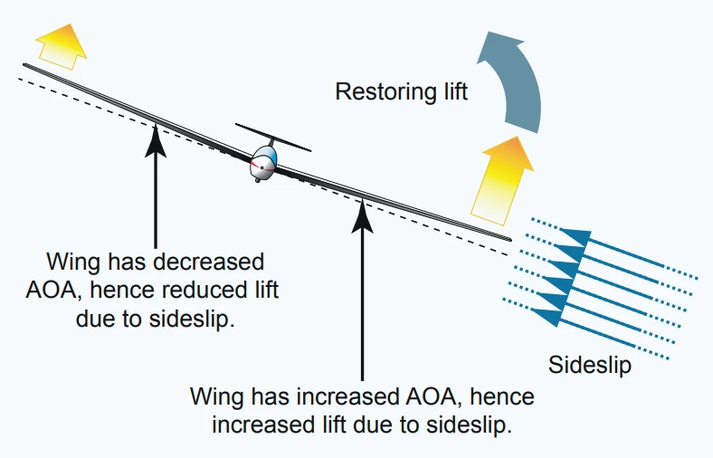
When an aircraft rolls to one side, the wing on the lower side (the side towards which the aircraft is turning) experiences a higher angle of attack compared to the wing on the higher side. This is due to the sideslip caused by the roll. This means the aircraft is also moving slightly sideways relative to its forward motion. The higher angle of attack on the lower wing generates more lift, which creates a rolling moment that helps level out the aircraft.
This increased lift on the lower wing helps to counteract the rolling tendency caused by the sideslip and keeps the aircraft flying straight and level. This makes it easier for pilots to maintain control and stability in the air.
However, it’s important to note that the primary control surfaces used for turning an aircraft are the ailerons and the rudder, not the dihedral angle of the wings. The dihedral angle mainly contributes to the stability of the aircraft during these maneuvers.
What is Coordinated Turn
A coordinated turn is a maneuver where the aircraft changes its direction while maintaining a balance of forces. This balance ensures that the passengers inside the aircraft do not experience any sideways push or pull during the turn.
In a coordinated turn, there is no sideslip. The aircraft’s entire body, including the wings and tail, are aligned with the direction of the turn. This is achieved by the pilot using the controls (ailerons, rudder, and elevator) in a coordinated manner.
From a technical perspective, a coordinated turn occurs when the aircraft’s tail aligns with its nose in the direction of the airflow. If the aircraft is not coordinated, it means that it is somewhat flying sideways relative to the airstream, causing the side of the fuselage to be exposed to the airflow.
A good turn is one in which the nose and tail of the aircraft track along the same path. This means that the aircraft is not slipping or skidding in the turn, but is moving smoothly along a curved path.
During a turn, if the aircraft isn’t perfectly coordinated, it can experience Sideslip or Skid. To keep the turn rate appropriate, the pilot can use more or less rudder going into a turn. A turn with too high a turn rate is known as a slip, while a turn with too little turn rate is a skid.
The pilot uses the slip indicator on the instrument panel to ensure they are flying a coordinated turn.
How to Achieve a Coordinated Turn:
Pilots achieve a coordinated turn by using all three control surfaces:
- Ailerons: Used to initiate the roll or bank the aircraft into the turn.
- Rudder: Used to counteract adverse yaw and ensure the nose of the aircraft points in the direction of the turn, minimizing sideslip.
- Elevator: Used to maintain altitude throughout the turn by adjusting the angle of attack and lift.
Slipping Turn vs Skidding Turn
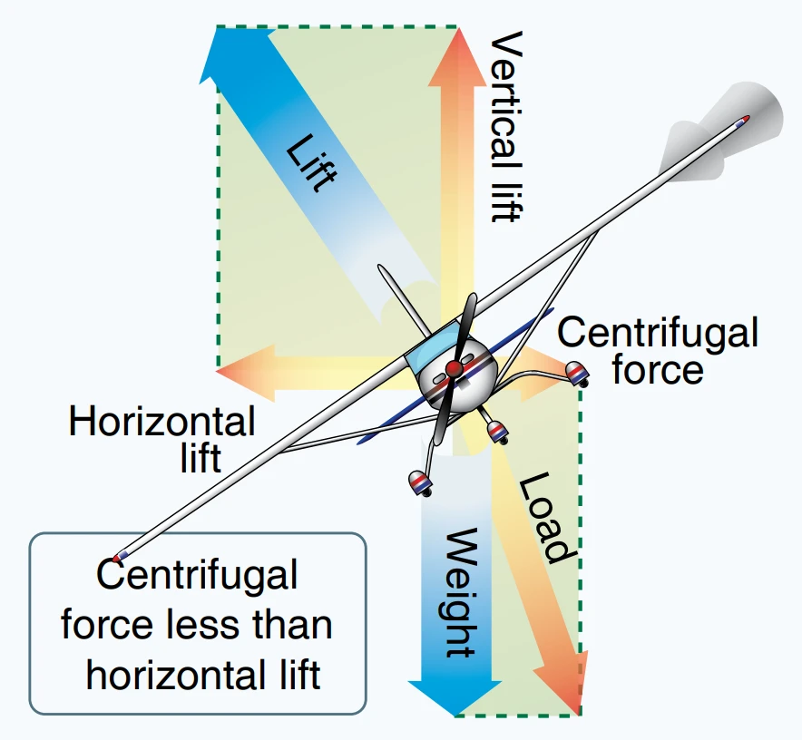
In a slipping turn, the aircraft is banked (tilted) too much for the rate at which it’s turning. This causes the aircraft to yaw, towards the outside of the turn. This happens because the horizontal lift component (the force that helps the aircraft turn) is greater than the centrifugal force (the force that pushes the aircraft outwards during a turn). To correct this, the pilot can increase the rate of turn, decrease the bank, or do both.
On the other hand, a skidding turn happens when the aircraft is not banked (tilted) enough for the rate of turn or the rate of turn is too great for the angle of bank. This results in the centrifugal force being greater than the horizontal lift component, which pulls the aircraft towards the outside of the turn. To correct a skidding turn, the pilot can decrease the rate of turn, increase the bank, or do both.
Slips are generally considered less dangerous than skids because the inside wing still generates some lift, while the outside wing in a skid might stall first.
Increased Load Factor During Turns
During a turn, the load factor increases because the centrifugal force (resulting from the curved flight path) adds to the weight of the aircraft. This increase in load factor affects stall speed and structural stress.
The stall speed increases proportionally to the square root of the load factor.
The load factor is the ratio of lift to weight. As the centrifugal force increases, the total force acting downward (weight + centrifugal force) becomes greater.
When an aircraft experiences increased load factors (such as during turns), it requires more lift. This necessitates flying at a higher AOA, which ultimately leads to a higher stall speed. Pilots must be aware of this effect during maneuvers to prevent inadvertent stalls.
The load factor is typically measured in Gs (acceleration due to gravity), which is a unit of force equivalent to the force exerted by gravity on a stationary body. Essentially, it indicates the force experienced by a body when it undergoes acceleration.
For example, a load factor of 3 means the total load on an aircraft’s structure is three times its weight. Since load factors are expressed in terms of Gs, a load factor of 3 may be spoken of as 3 Gs, or a load factor of 4 as 4 Gs.
When any external force is applied to an aircraft, causing it to deviate from a straight flight path, it generates stress on the aircraft’s structure. This force magnitude is precisely what we refer to as the load factor.
Note: Load factors become significant to both flight performance and load on wing structure as the bank increases beyond approximately 45°.
Remember that load factor plays a critical role in flight safety and structural integrity. Pilots must be aware of load factors during maneuvers, turns, and other flight conditions to ensure the aircraft remains within safe limits.
Turning the Aircraft using Autopilot
Modern aircraft are equipped with advanced autopilot systems that can perform a variety of tasks, including turning the aircraft. The autopilot system uses a combination of onboard sensors, computers, and actuators to control the aircraft’s flight path.
When the autopilot is engaged and a new heading is selected, the following happens:
- The autopilot system computes the required bank angle for the turn.
- The Flight Control System moves the ailerons to roll the aircraft to the computed bank angle.
- The yaw damper automatically adjusts the rudder to counteract any adverse yaw and keep the turn coordinated.
- The elevators are used to maintain altitude during the turn.
- The auto-throttle adjusts the thrust to maintain speed during the turn.
Modern autopilot systems also include various protections to ensure safe flight:
- Bank Angle Protection: Prevents the aircraft from exceeding a certain bank angle during turns.
- Overspeed and Stall Protection: Adjust the aircraft’s pitch and power settings to prevent the aircraft from flying too fast or too slow.
- Altitude Protection: Prevent the aircraft from deviating too far from the selected altitude.
- Load Factor Protection: Prevents maneuvers that would subject the aircraft to excessive g-forces.
Use of Yaw Damper
Adverse yaw is a tendency for an aircraft to yaw in the opposite direction of a roll. This is typically more pronounced in aircraft with ailerons, as the downward-deflected aileron produces more lift (and thus more drag) than the upward-deflected one, causing the aircraft to yaw towards the wing with the downward aileron.
The yaw damper can help mitigate this effect. It does so by automatically providing rudder input to counteract the yawing motion caused by the ailerons.
A yaw damper is an automated system used in aircraft to reduce the oscillations in yaw and roll, a phenomenon known as Dutch roll. It enhances the smoothness and stability of the aircraft’s flight by counteracting these unwanted yawing motions. However, it does not inhibit intentional yaw, such as that commanded by the pilot during a turn.
Dutch roll is not specifically associated with turning maneuvers. It can occur in straight and level flight, particularly if the aircraft is disturbed by turbulence.
The Yaw damper’s primary function is to dampen Dutch roll oscillations, but it also contributes to reducing adverse yaw, particularly during turning maneuvers when the autopilot is engaged.
Rate of Turn and Turn Radius
The rate of turn is the angular change per unit time, while the turn radius is the horizontal distance traveled during a turn. Both parameters are influenced by factors such as bank angle and airspeed.
The rate of turn refers to how quickly an aircraft changes its heading. It is usually measured in degrees per second. For example, a standard rate turn, also known as a rate one turn, is defined as a 3° per second turn, which completes a 360° turn in 2 minutes.
The radius of turn at any given bank angle is directly proportional to the square of the airspeed. Doubling the airspeed results in a radius of turn that is four times greater, while tripling the airspeed would result in a radius that is nine times greater. Conversely, if the aircraft speed remains constant, increasing the bank angle will decrease the turn radius.
Types of Aircraft Turns: Standard vs Steep
Aircraft turns are categorized based on their bank angle or rate of turn. Here are some common types of turns:
Standard Rate Turn
A standard rate turn, also known as a two-minute turn, is a turn in which the aircraft changes its heading by 360 degrees in two minutes. This equates to a turn rate of 3 degrees per second. Standard rate turns are used in instrument flying and air traffic control.
Half Standard Rate Turn
A half standard rate turn is a slower turn, in which the aircraft changes its heading by 360 degrees in four minutes. This equates to a turn rate of 1.5 degrees per second. Half-standard rate turns are often used in larger aircraft, which have slower roll rates.
Steep Turn
A steep turn is a turn in which the bank angle is greater than 30 degrees. In general aviation, a steep turn is often defined as a turn with a bank angle of 45 degrees. Steep turns require more lift to maintain altitude, which means the aircraft must fly at a higher angle of attack or a higher airspeed.