A320 ATA 22 Technical Notes are brief and to-the-point information about the Airbus A320 Auto Flight System, including its components and their functions. ATA Chapter 22 is titled Auto Flight, which covers automatic control of flight, including flight management, flight guidance, and flight augmentation.
A320 Auto Flight System
The Airbus A320 Auto Flight System is made up of the Flight Management and Guidance System (FMGS) and Flight Augmentation System (FAS).
The FMGS performs the functions: autopilot (AP); flight director (FD); autothrust (A/THR); and flight management, which includes navigation, performance, and processing of displays.
The FAS performs the functions: yaw damper; rudder travel limiting; monitoring of the flight envelope and computations of maneuvering speed; yaw autopilot order using power loops of yaw damper and rudder trim; and BITE function of the AFS by FAC 1.
AUTO FLIGHT – TECHNICAL POINTS
- Automatic Flight System (AFS) calculates orders to automatically control the flight controls and the engines. It computes orders and sends them to –
- Electrical Flight Control System (EFCS) to control flying surfaces, and
- Full Authority Digital Engine Control (FADEC) to control engines.
- When the AFS is not active, orders are generated by –
- Side Sticks, and sends them to EFCS to control flying surfaces.
- Thrust Levers, and sends them to FADEC to control engines.
- During AFS operation, side sticks and thrust levers do not move automatically.
- If the pilot moves the side stick when the AFS is active, it disengages the autopilot. Back to manual flight, when the sidestick is released, the EFCS maintains the actual aircraft attitude.
The Auto Flight System (AFS) is divided into four main parts:
- Flight Management (FM) – function accomplished by FMGCs.
- Flight Guidance (FG) – function accomplished by FMGCs.
- Flight Augmentation – function accomplished by FACs.
- Fault Isolation and Detection System (FIDS) – function accomplished by FAC1.
AFS is designed around –
- 2 FMGC – Flight Management and Guidance Computer
- 2 FAC – Flight Augmentation Computer
- 2 MCDU – Multipurpose Control and Display Unit
- 1 FCU – Flight Control Unit
To meet the necessary reliability, the AFS is built around 4 computers. There are two interchangeable Flight Management and Guidance Computers (FMGCs) and two interchangeable Flight Augmentation Computers (FACs). It is a FAIL OPERATIVE system. Each FMGC and FAC has a command (CMD) part and a monitor (MON) part to be FAIL PASSIVE.
Both FACs are interchangeable. FIDS function accomplished by FAC 1. Pin Programming for FIDS is on the interface (where FAC1 connects) not on the FAC (computer).
FMGC – TECHNICAL POINTS
FMGC performs the functions given below –
- Flight Management functions
- Navigation Functions
- Computation of position
- Radio navigation tuning
- Alignment of Inertial Reference System
- Management of Flight Plan – Construction and Follow-up
- Optimizing flight plan to reduce cost
- Predictions for primary and secondary flight plans and display them on MCDU & ND.
- Management of display on MCDU/PFD/ND
- Navigation Functions
- Flight Guidance functions
- Autopilot
- Flight Director
- Autothrust
Flight Management has four modes of operation:
- Normal Mode – Dual Mode (Both FMGC)
- Independent Mode – Each FMGC is controlled by its associated MCDU
- Single Mode – using one FMGC only
- Back-up Navigation Mode – in case both FMGC fails (optional system)
Flight Guidance
- Managed modes – Long-term pilot orders are entered through the MCDU.
- Selected modes – Short-term pilot orders are entered through the FCU.
- Selected guidance always has priority over managed guidance.
AUTOPILOT (AP)
- Stabilizes the aircraft around its center of gravity,
- Acquires and tracks a flight path, and
- Flies the aircraft to an automatic landing or go-around.
- If the airfield is equipped with ILS installations, the AP can perform a complete landing with approach, flare and roll out. >> AUTO LAND (AP engaged in LAND mode).
- The autopilot gives orders to control – (FMGC send the commands)
- the position of the control surfaces on the three axes: pitch, roll and yaw.
- the position of the nose wheel.
- These orders are taken into account by these computers: FACs, ELACs, SECs and BSCU.
- AP Modes –
- Lateral modes – guide the aircraft in lateral path.
- Vertical modes – guide the aircraft in vertical path.
- Basically, one of each mode is chosen by the pilot or by the system.
- According to flight phases,
- Lateral mode controls:
- Ailerons via the ELACs,
- Spoilers via the ELACs and SECs,
- Rudder via FACs,
- Nose wheel via the ELACs and BSCU.
- Vertical mode controls the elevators and the THS via the ELACs.
- Lateral mode controls:
- The AP being engaged, one lateral mode and one vertical mode are simultaneously active.
- The AP can be engaged only after takeoff.
- by means of the AP1 and AP2 p/b switches on FCU.
- AP1 has priority, AP2 is in standby.
- For maintenance purposes, AP can be engaged on ground with both engines shut down. When an engine is started, the AP disengages.
- When the AP is engaged, the load thresholds on the rudder pedals and the side sticks are increased. If a pedal or side stick load threshold is overridden, the AP disengages.
- AP disengages when the pilot –
- Presses the takeover pb on the sidestick, or
- Presses the corresponding AP pb on the FCU, or
- Pushes on the sidestick harder than a defined threshold, or moves on the rudder pedals beyond a defined threshold.
- The standard way for the flight crew to disengage the AP is to press the takeover pb on the sidestick.
- The side stick controllers do not move when the autopilot is engaged.
FLIGHT DIRECTOR (FD)
- FD displays the guidance commands on both PFDs, allowing the pilots to fly the aircraft manually according to the FMGC demands. Two cases have to be considered –
- AP not engaged: FD function displays symbols on the PFD which gives orders to the pilot to maintain the desired parameters. In this case, the pilot follows these orders by acting on the flight controls.
- AP engaged: FD function displays symbols on the PFD representing the AP orders to be monitored by the pilot.
- In normal operations –
- FD1 displays FMGC1 orders on the PFD1, and
- FD2 displays FMGC2 orders on the PFD2.
- The FDs are engaged automatically when the FMGC powers up.
- The flight crew may disengage one or two FDs manually.
- FDs may disengage automatically if there is a failure.
- The FD pb on the EFIS control panel allows the FD bars to be displayed or removed.
- FD is only a display system, not controlling anything – guidance only.
AUTOTHRUST (A/THR)
- A/THR function can be ENGAGED or DISENGAGED.
- When it is engaged, it can be ACTIVE or NOT ACTIVE.
- ENGAGED
- ACTIVE – A/THR system controls the engines,
- NOT ACTIVE – Thrust levers control the engines as long as a thrust lever is outside the A/THR active area,
- DISENGAGED
- Thrust levers control the engines, when A/THR function is disengaged.
- FADECs compute the thrust limit, depending on the position of the thrust levers.
- Thrust levers are manually operated and electrically connected to FADEC.
- A/THR has two systems, one per FMGC – A/THR 1 & A/THR 2.
- Auto engage – when some conditions are fulfilled.
- Manual engage – A/THR p/b on FCU.
- A/THR can operate independently or with the AP/FD.
- Both A/THRs are always engaged at the same time but only one is active depending on AP and FD engagement status.
- A/THR has 3 mode of operation
- THRUST mode
- SPEED/MACH mode
- RETARD mode
- A/THR is disengaged by –
- Pressing A/THR instinctive disconnect switch on any thrust lever, or
- Setting all thrust levers to idle position, or
- Pressing A/THR P/B on FCU.
- A/THR is automatically disengaged in case of failure detection.
- When the A/THR function is active, the actual engine thrust does not necessarily correspond to the thrust lever position. >> Thrust Lever does not move.
MCDU & FCU
- MCDU permit to enter and display a flight plan and the control parameters required by the FMGCs for flight control.
- FCU transmits the modes and the references selected by the pilots to the FMGCs.
- The Flight Control Unit (FCU) is located on the glareshield and is constituted of three control panels:
- One for the automatic flight controls and
- Two for the Electronic Flight Instrument System (EFIS).
- The FCU consists of two identical computers totally independent.
FAC – TECHNICAL POINTS
FAC performs the functions
- Yaw damping – by using yaw dampers
- Rudder trim – manual or automatic
- Rudder travel limitation
- Flight Envelope Protection
- BITE function of the AFS in FAC 1 (FIDS)
YAW DAMPER
- Yaw damper has four functions and controls the rudder via yaw damper actuators.
- Upon FMGC, ELAC or FAC orders, the yaw damper provides:
- dutch roll damping,
- turn coordination in cruise,
- engine failure compensation in auto flight,
- yaw guidance order execution.
- There are two yaw dampers. In normal operation, both are engaged but only one is active.
- The yaw damper actuator does not move the rudder pedals.
- Yaw damper actuator 1 – Green hydraulic system.
- Yaw damper actuator 2 – Yellow hydraulic system.
- Yaw Damper Position Transducer Unit.
RUDDER TRIM
- The rudder trim gives:
- Manual trim with RUD TRIM selector,
- Auto trim on yaw axis and the generation of engine failure recovery function when the autopilot is engaged.
- Rudder trim orders come from the Rudder Trim Selector Knob via FAC to control the rudder via the Rudder Trim Actuator.
- When the AP is engaged, the rudder trim selector knob is inoperative, – FMGC sends rudder trim orders to the FAC.
- Rudder Trim Reset P/B Switch
- Rudder Trim Indicator
RUDDER TRAVEL LIMITING
- Limits the deflection for structure integrity,
- Prevents excessive deflections which would penalize the aircraft performance.
- The rudder travel limitation is computed by the FAC and sent to the Rudder Travel Limiting Unit (RTLU).
FLIGHT ENVELOPE PROTECTION
For flight envelope protection, the FAC computes:
- Various speeds for aircraft operation (e.g. flaps limit speed),
- Excessive angle of attack and windshear detection, – “WINDSHEAR, WINDSHEAR, WINDSHEAR”
- This WINDSHEAR is Active Windshear, not confused with Predictive Windshear.
- ACTIVE WINDSHEAR – Protection by FAC.
- PREDICTIVE WINDSHEAR – Protection by PWS function in WXR.
- This WINDSHEAR is Active Windshear, not confused with Predictive Windshear.
- Alpha-floor detection to the FMGCs for A/THR engagement, if it is not engaged,
- Low energy warning, indicating to the crew that the aircraft is quickly decelerating and that thrust will have to be increased to recover a positive flight path angle through pitch control, – “SPEED SPEED SPEED“
- Warning for Tail Strike Protection. “PITCH-PITCH“
- FAC also computes the weight and the center of gravity.
FAC 1: BITE Function
- FAC 1 is connected to the BITE of all the AFS computers and communicates to the CFDS.
- FIDS card is physically located in the FAC1 and is activated.
- FIDS serves as the SYSTEM BITE (maintenance data concentrator).
- The FIDS is linked in acquisition and reception to the centralized fault-display interface-unit (CFDIU) and is connected to the BITEs of the various AFS computers.
A320 Auto Flight Schematic
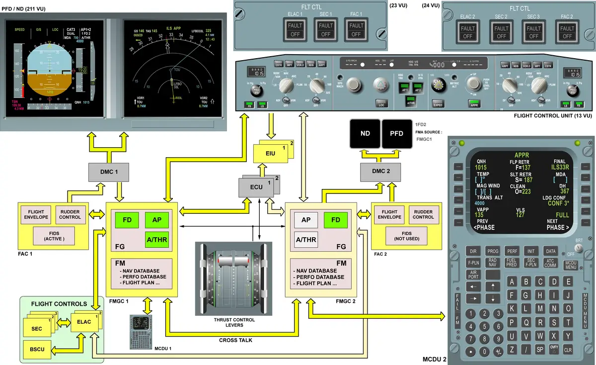
COMPUTERS
- FMGC – 2
- FAC – 2
- FCU – 1
- MCDU – 2
See the location of A320 Computers.
CONTROLS AND INDICATIONS
- FLIGHT CONTROL PANEL
- FLIGHT CONTROL UNIT
- EFIS CONTROL PANEL
- THRUST LEVER & PITCH TRIM
- INDICATIONS ON PFD
- INDICATIONS ON ND
- MCDU
THRUST LEVERS
The thrust levers can be moved on a sector which includes specific positions:
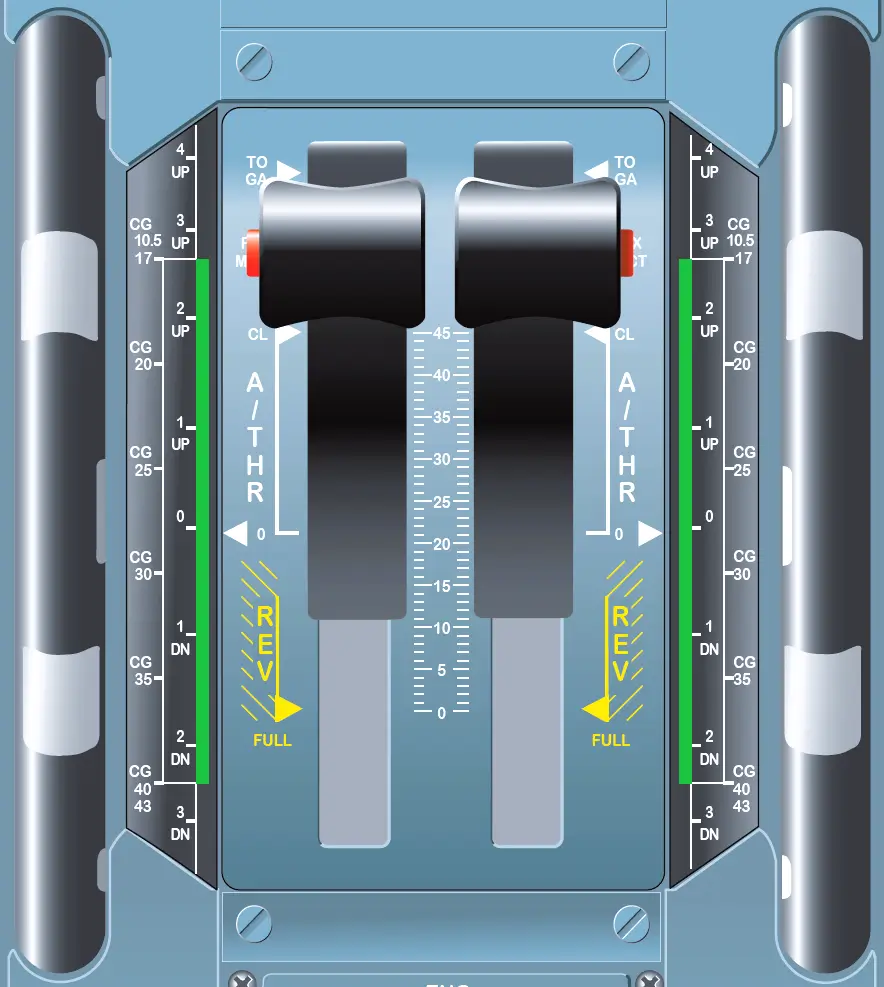
- Rear section: for idle reverse up to max reverse.
- Center section:
- 0: corresponds to an idle thrust,
- CL: corresponds to a climb thrust.
- Forward section:
- FLX/MCT: corresponds to a FLeXible take-off thrust or a Maximum Continuous Thrust after an engine failure,
- TOGA: corresponds to a maximum Takeoff/Go Around thrust.
OTHER POINTS
FMS AOC FUNCTIONS
The Flight Management System (FMS) AOC function serves as an interface between a ground station and an onboard Flight Management and Guidance Computer (FMGC). It allows data exchange between these two computers via either the Aircraft Communications Addressing and Reporting System (ACARS) Management Unit or the Air Traffic Services Unit (ATSU).
Two different sets of messages can be exchanged:
- UPLINK messages originate from the ground station. They involve receiving requested data or direct communication with the flight crew.
- DOWNLINK messages originate from the FMGC (acting as the master). These messages include reports or requests sent to the ground station.
The FMGS/ACARS or FMGS/ATSU interface enables several AOC (Aircraft Operations Control) capabilities, including:
- F-PLN initialization (setting up the flight plan and performance data).
- Takeoff data management.
- Wind data handling.
- Flight reports generation.
- Broadcast data dissemination.
Crews can send messages using the ACARS FUNCTION pages or relevant MCDU (Multipurpose Control and Display Unit) pages. Importantly, only one FMGC communicates with the ground station, and this specific FMGC is known as the FMGC master.
FLIGHT PLANNING
FLIGHT PLANNING > FLIGHT MANAGEMENT DATABASES
- Navigation Database – contains standard navigation data like navaids, waypoints, airways, enroute information, and airports.
- Performance Database – contains aircraft performance related data. Airlines can modify this database.
FLIGHT PLANNING > ACARS FUNCTION
- The Flight Management uses the Aircraft Communication Addressing and Reporting System (ACARS) function to exchange data between the ground station and FMGC via the ATSU.
- This interface makes the exchange of flight plan initialization, take-off, wind, and broadcast data and flight reports with the ground. Via the ACARS, the crew may send a request for wind data to the ground. In response to this request, or automatically, the ground sends climb, cruise, descent and alternate wind data to the aircraft.
EFIS DISPLAYS
- Four EFIS displays, i.e. two PFDs and two NDs.
- Flight parameters are displayed on the PFDs.
- Flight plan and navigation data are displayed on the NDs.
- FMA is the top part of the PFD.
FLIGHT MODE ANNUNCIATOR (FMA)
- The three types of information on the FMA are:
- A/THR mode/status,
- AP/FD mode and status,
- Flight Management (FM) messages.
- FMA Comprises 3 lines and 5 column
APPROACH MODE
The aircraft can fly different types of approaches:
- Precision approaches: ILS, (MLS – Military).
- Non-precision approaches: VOR/DME, VOR, NDB (if ADF), RNAV.
- Non-precision approaches using a Localizer only: LOC.
LANDING CAPABILITIES
Each FMGC computes its own automatic landing capability.
- FMA displays “CAT 1”, “CAT 2”, “CAT 3 SINGLE” or “CAT 3 DUAL”.