A320 ATA 24 Technical Notes are brief and to-the-point information about the Airbus A320 Electrical Power System, including its components and their functions. ATA Chapter 24 is titled Electrical Power, which covers AC and DC Generation, Load Distribution, and Emergency Power Systems.
A320 Electrical Power System
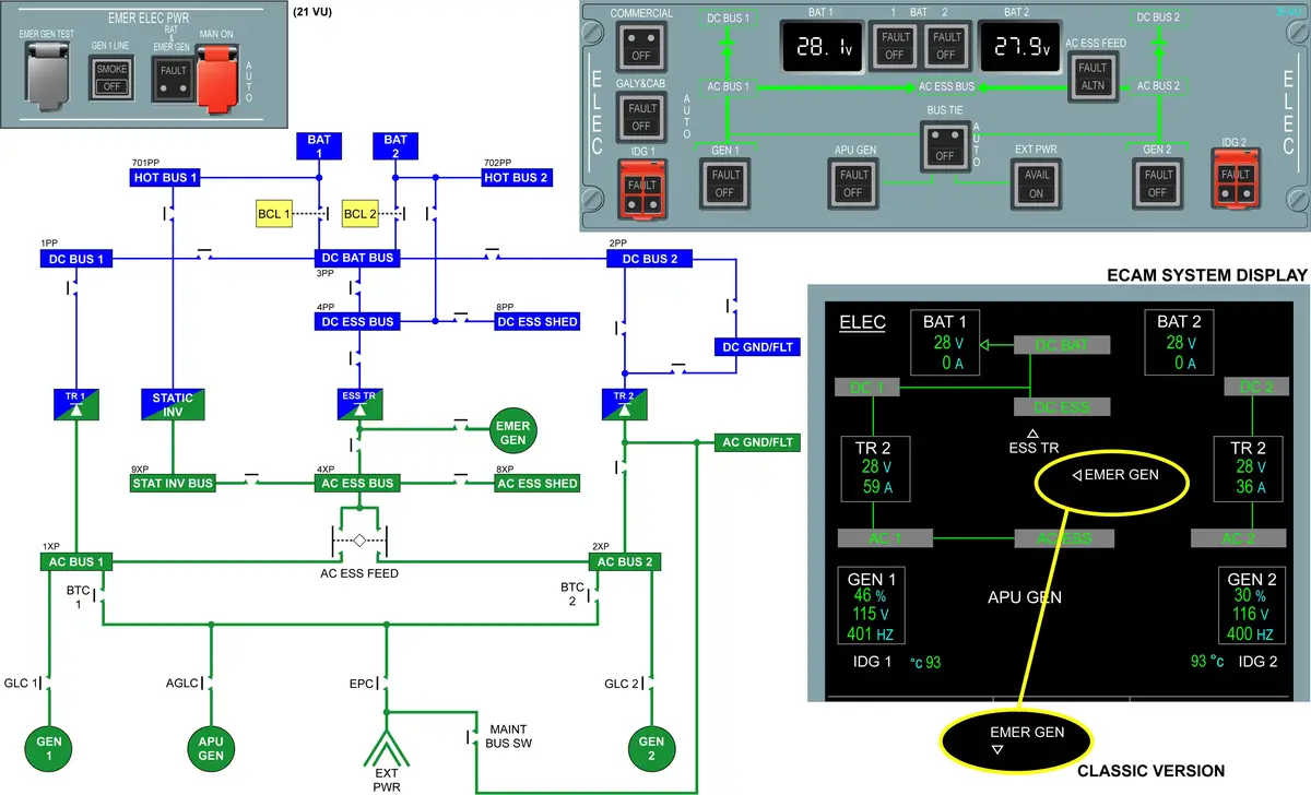
The Airbus A320 Electrical Power System consists of a three-phase 115/200 V 400 Hz constant-frequency AC system and a 28 V DC system. The system is composed of 2 engine generators and 1 APU generator. Each generator can provide AC power to all electrical bus bars.
Some AC power is converted into DC power for certain applications. In case the normal AC power is not available, an emergency generator can provide AC power. If all AC power is not available, the electrical power system can invert DC power from the batteries into AC power.
- A320 is basically AC operated aircraft.
- Electrical Power System
- 115/200V 3 Phase 400Hz constant-frequency AC system
- 28V DC system
- 115 V – Phase Voltage (b/w phase and neutral)
- 200 V – Line Voltage (b/w phase and phase)
AC GENERATION
- MAIN GENERATORS
- 115/200 volts, 3 Phase, 400 Hz, 90 KVA
- GEN 1 (IDG 1) – ENG 1
- GEN 2 (IDG 2) – ENG 2
- Each IDG is controlled and monitored by its GCU.
- GEN 1 – GCU 1
- GEN 2 – GCU 2
- APU GENERATOR & EXTERNAL POWER
- 115/200 volts, 3 Phase, 400 Hz, 90 KVA
- APU GEN – APU
- EXT PWR – GPU
- APU Generator can replace one or both main engine generators throughout the flight envelope.
- A Ground and Auxiliary Power Control Unit (GAPCU) controls both the APU generator and the EXT PWR.
- EMERGENCY GENERATOR
- 115/200 volts, 3 Phase, 400 Hz, 5 KVA (NEO – 5.4 KVA)
- EMER GEN (CSM/G) – RAT Hydraulic Circuit
- STATIC INVERTER
- 115 volts, 1 Phase, 400 Hz, 1 KVA
- STAT INV – DC Power from Battery1
- When the aircraft speed is above 50 kt, the inverter is automatically activated, if nothing but the batteries are supplying electrical power to the aircraft, regardless of the BAT 1 and BAT 2 pushbutton positions.
- When the aircraft speed is below 50 kt, the inverter is activated, if nothing but the batteries are supplying electrical power to the aircraft, and the BAT 1 and BAT 2 pushbuttons are both on at auto.
AC DISTRIBUTION
- AC BUS 1 – Supplied by ENG 1 GEN.
- AC BUS 2 – Supplied by ENG 2 GEN.
- AC ESS BUS – Normally supplied by AC BUS 1 or by AC BUS 2 if AC BUS 1 fails.
- AC ESS SHED BUS – Supplied by AC ESS BUS.
- AC STAT INV BUS – STAT INV connected to Battery 1 supplies the AC STAT INV BUS.
- 26V AC BUS – Supplied by 115/26V AUTO TRANSFORMER.
DC GENERATION
- TRANSFORMER RECTIFIERS (TRs) – UP TO 200 A OF DC
- TR1 – AC BUS 1 (GEN1)
- TR2 – AC BUS 2 (GEN2)
- ESSENTIAL TR – EMER GEN
- BATTERIES
- Normal capacity of 23 AH (NEO – 28 AH) with a nominal voltage of 24V.
- Permanently connected to the two hot buses.
- Each battery has an associated Battery Charge Limiter (BCL).
- The BCL monitors battery charging and controls its battery contactor.
- BAT 1 – BCL 1
- BAT 2 – BCL 2
- COMPLETE DISCHARGE PROTECTION – On ground, when the battery voltage is lower than 23V DC for 15 s, the BCL supply contactor opens automatically.
DC DISTRIBUTION
- DC BUS 1 – Supplied by TR1
- DC BUS 2 – Supplied by TR2
- DC BAT BUS – Supplied by DC BUS 1 or by DC BUS 2 if DC BUS 1 fails. Batteries can also supply DC BAT BUS.
- DC ESS BUS – Supplied by DC BAT BUS. In emergency, it is supplied either by battery 2 or by essential TR.
- DC ESS SHED BUS – Supplied by the DC ESS BUS.
- HOT BUS 1 – Permanently supplied by Battery 1.
- HOT BUS 2 – Permanently supplied by Battery 2.
BUSBAR SYSTEM
- Split Busbar System – Two supplies cannot be connected together.
- That’s why – Priority Logics.
AC POWER TRANSFER
The transfer circuit enables the supply of either AC electrical network or both from one of the four power sources (GEN 1, GEN 2, APU GEN, EXT PWR) via the Bus Transfer Contactors (BTC). BTC control is entirely automatic and depends on the availability of these sources and the correct condition of each network.
BTC’s 1 and 2 can be locked out by pressing BUS TIE pushbutton switch located on ELEC overhead panel. This causes both channels to be isolated.
PRIORITY LOGICS
- 1 – Onside generator (IDG)
- 2 – External power
- 3 – APU GEN
- 4 – Offside generator (IDG)
BUS BAR IDENTIFICATION
- XP – AC
- PP – DC
GROUND SERVICE
- GROUND/FLIGHT BUSES
- AC GND/FLT BUS
- DC GND/FLT BUS
- Normally supplied by the aircraft network, or directly by the external power unit, upstream of the External Power Contactor (EPC), without energizing the whole aircraft network.
- On ground, when only ground services are required, external power can supply the AC and DC GND/FLT BUSES directly without supplying the entire aircraft network. Personnel select this configuration with the MAINT BUS switch in the forward entrance area.
- DC GND/FLT BUS through TR2.
NORMAL FLIGHT CONFIGURATION
- IDG 1 > AC BUS 1 > TR 1 > DC BUS 1 > DC BAT BUS < BAT 1 > HOT BUS 1 & BAT 2 > HOT BUS 2.
- AC BUS 1 > AC ESS > AC ESS SHED
- DC BAT BUS > DC ESS > DC ESS SHED
- IDG 2 > AC BUS 2 > TR 2 > DC BUS 2
- AC BUS 2 > AC GRND FLT
- DC BUS 2 > DC GRND FLT
EMERGENCY CONFIGURATION
- RAT deployment conditions –
- AC BUS 1 & AC BUS 2 – FAIL
- Speed > 100 KTS
- L/G not compressed – A/C in flight
- EMER GEN > AC ESS > AC ESS SHED
- EMER GEN > ESS TR > DC ESS > DC ESS SHED
NORMAL TO EMERGENCY
- During time gap – before emergency gen connection. Till the time –
- BAT 1 > STAT INV > AC STAT INV
- BAT 1 > HOT BUS 1
- BAT 2 > DC ESS
- BAT 2 > HOT BUS 2
- When speed < 100 kts – EMER GEN deactivated.
- 50 to 100 kts – DC BAT BUS recovered.
- Below 50 kts – AC ESS BUS disconnected.
- < 100 kts conditions – usually after landing.
IDG
- Integrated Drive Generator consists of a – mounted side by side in a single housing.
- Constant Speed Drive (CSD) and
- AC Generator
- CSD components convert a variable input speed to a constant output speed.
- CSD portion of the IDG is a hydromechanical device that adds to or subtracts from the variable input speed of the engine gearbox.
- IDG is cooled and lubricated by the oil circulation system.
- Oil is cooled by an external mounted IDG oil cooler.
- IDG oil outlet temp. – display on SD.
- IDG over voltage – 130 +/- 1.5 v
- IDG over frequency – 435 +/- 1 Hz
- IDG – PMG > 16 pole
- GCU supply
- Exciter field of generator for voltage regulation
If IDG HIGH OIL TEMP / LOW OIL PRESSURE
- Indication –
- Master caution
- Single chime
- ELEC IDG 1 (2) OIL OVHT / ELEC IDG 1 (2) LO PR
- IDG p/b – Fault light
- Action –
- IDG must be disconnected by P/B manually.
- Push IDG disconnection p/b for max of 3 sec.
- Don’t press for more than 3 sec. because the IDG thermal disconnect solenoid is high current solenoid. It can burn/damage the solenoid.
- Disconnection is only possible when the engine is running above underspeed.
- Disconnection – Rod > push > hit > disconnect. Push by thermal disconnect solenoid.
- Connection – Pull the reset ring.
GEN P/B
- Used to connect or disconnect the generator output to or from the Bus Bar, and
- To reset the GCU.
- GEN 1, APU GEN, GEN 2 – P/B
- P/B controls the GEN LINE CONTACTORS (GLCs) – 3 for each GEN.
- GLC connects the generator to its own bus bar.
IDG P/B
- IDG1, IDG2 – P/B
- IDG P/BSW is used for manual disconnection of IDG from the engine gearbox.
- With the engine stopped, the IDG cannot be manually disconnected.
- IDG disconnection is achieved by a solenoid activated clutch.
- IDG P/B FAULT legend comes on if the IDG oil pressure is less than 140 psi or if the IDG oil outlet temperature is above 185°C. In both conditions, the IDG must immediately be disconnected. When the IDG P/B is pushed, the FAULT legend goes out.
IDG THERMAL DISCONNECT
- If the temperature reaches 200°C, a solder fuse melts and automatically releases the disconnect mechanism to open the IDG disconnect clutch. (To protect the IDG). A warning message is sent to the ECAM system and a BITE MESSAGE (THERMAL DISCONNECT) is sent to the CFDS.
- After a thermal disconnection, the IDG must be replaced.
OPERATIONAL TEST OF THE IDG DISCONNECT AND RECONNECT FUNCTION
- Push the IDG 1 (2) P/BSW.
- On the IDG 1 (2), slowly pull out the disconnect reset ring to the full limit of travel. If you feel a click while you hold the disconnect reset ring, this shows that the disconnect function operates correctly. Let the disconnect reset ring go slowly back to the initial position.
- The IDG disconnection is irreversible in flight.
- Reconnection of the system is then possible only on the ground with engines shut down.
IDG SERVICE TIPS
- Fill the IDG with oils at a maximum pressure of 35 PSI.
- When servicing, leave the drain hose attached until only a couple of drops come out. >> avoid overservicing.
GEN 1 LINE P/B
- In SMOKE configuration – Red SMOKE Light ON. (Avionics Smoke)
- On activation of this p/b opens GLCs.
- Fuel pumps are connected upstream of the GEN 1 GLC.
- Generator stays energized to supply directly the fuel pumps 1 LH and 1 RH side.
APU GEN
- APU generator is cooled and lubricated by the APU oil.
- In case of oil temperature above 185°C, ECB commands > To shutdown the APU.
- APU speed is not variable that’s why there is no CSD. Speed is almost constant. Speed control by FCU.
EXT POWER
- External power has priority over the APU generator. The engine generators have priority over external power.
- ON light stays on, even when the engine generators supply the aircraft.
- Environmental Precautions – Avoid use of the APU if APU BLEED air is not necessary.
EXT PWR RECEPTACLE
- 3 phase – 3 pin – A , B , C
- 1 neutral – 1 pin – N
- 2 small pin – E , F
- DC supply to GAPCU – for control and protection, and validity of connection.
- Reason for small – A, B, C pin properly connected then only E , F allow to supply the power.
SHORT CIRCUIT PROTECTION – PTC (for EXT power only)
- Positive Temp. Coefficient Sensor
- Red PTC trip LED on GAPCU
EMR GEN
- Hydraulic motor is pressurized by the blue hydraulic system through an integrated solenoid valve. The hydraulic motor speed is regulated by a servo valve.
- If both AC BUS 1 and AC BUS 2 are lost and the aircraft speed is above 100 kt, the Ram Air Turbine (RAT) extends automatically.
- If AC BUS 1 and 2 are lost and the RAT does not extend, FAULT light comes on red on the EMERgency ELECtrical PoWeR panel (this is only indication not a p/b, that fault light is controlled by BCL). The RAT must be manually extended to power the emergency generator. This is done by pressing the guarded MANual ON P/BSW on the EMER ELEC PWR panel.
- RAT MAN ON P/BSW on the blue hydraulic panel enables the extension of the RAT for hydraulic power supply only.
- Activation of the red guarded “MAN ON” p/b on the ground or in flight will extend the RAT even on COLD AIRCRAFT.
RAT SOLENOID
- Two – Solenoid 1 & Solenoid 2
- Hot Bus supply – only – RAT MAN p/b (hyd panel) & Solenoid 1
- p/b can deploy the RAT even if a/c is in cold condition.
- RAT p/b on elec panel – not connected to Hot Bus.
- Solenoid 1 – for auto deploy
- Solenoid 2 – for manual deploy
CFDIU INTERFACE
- GAPCU has an interface with CFDIU
- GCU 1 / GCU 2 > GAPCU > CFDIU
- CSM/G GCU – directly to CFDIU
CIRCUIT BREAKERS
The aircraft has two types of C/Bs:
- Monitored (Green): When out for more than 1 min, the C/B TRIPPED warning is triggered on the ECAM.
- Non-monitored (Black).
- Wing Tip Brake (WTB) C/Bs have red caps on them to prevent them from being reset.
- C/B TRIPPED warning on the ECAM indicates the location of the affected C/B.
CONTROLS AND INDICATIONS
COMPUTERS
- GCU
- GAPCU
See the location of A320 Computers.