A320 ECAM ELEC PAGE
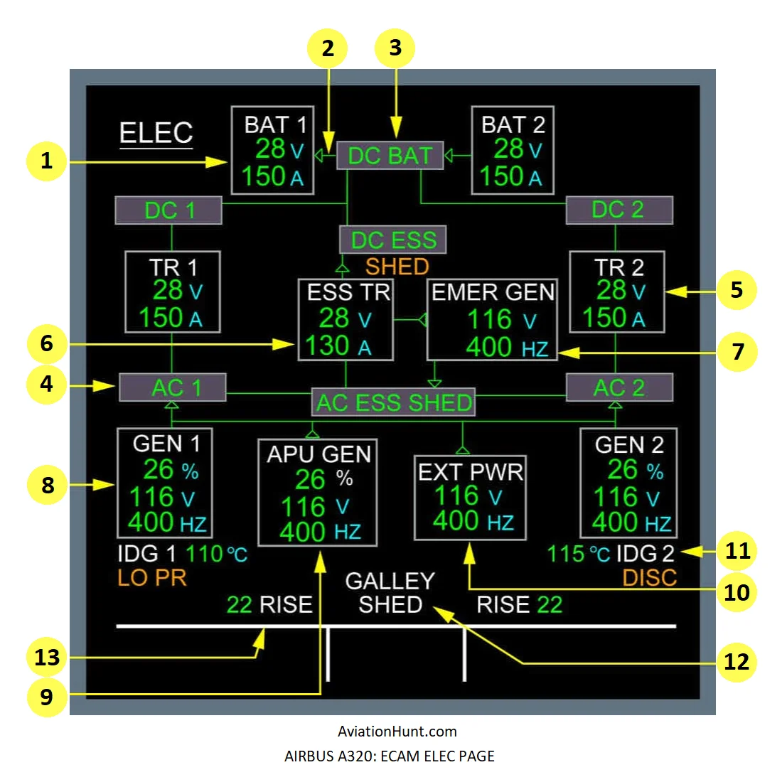
The A320 ECAM ELEC page with its parameters is described in the image above as follows:
- 1: Battery indications
- 2: Battery charge/discharge indication
- 3: DC BAT indication
- 4: Bus bar indication
- 5: TR 1(2) indication
- 6: ESS TR indication
- 7: EMER GEN indication
- 8: GEN 1(2) indications
- 9: APU GEN indications
- 10: EXT PWR indications
- 11: IDG indications
- 12: GALLEY SHED indication
- 13: RISE indication
Reference Aircraft: A320neo/LEAP-1A26
1. Battery indications
- BAT pb-sw at OFF: Legend is in white.
- BAT pb-sw at Auto: Legend is normally white, but becomes amber when voltage and current indications change to amber, or in case of a BAT FAULT warning.
- Battery voltage is normally green, but becomes amber if V > 31 V or V < 25 V.
- Battery current is normally green, but becomes amber if discharge current > 5 A.
- The digital values for the voltage or the current are replaced by amber XX when the related data are not available from the SDAC.
2. Battery charge/discharge indication
- Green color link with arrow points to battery: Battery contactor closed. Battery charging current is above 1 A.
- Amber color link with arrow points away from battery: Battery contactor closed. Battery discharge current is above 1 A.
- Green color link with no arrow: Battery contactor closed. Battery current is less than 1 A.
- No link: Battery contactor open.
3. DC BAT indication
- It is normally in green. It becomes amber, if DC BAT voltage ≤ 25 V.
4. Bus indication
- It is normally in green. It becomes amber, when the corresponding bus is off.
- SHED appears in amber, when AC or DC SHED ESS BUS is off.
- The space for SHED is blank if the bus is not shed, or when the information is not available from the SDAC.
5. TR 1 (2) indication
- It is normally in white. It becomes amber when TR voltage and TR current indication becomes amber.
- The TR voltage is normally in green. It becomes amber, if V > 31 V, or V < 25 V.
- The TR current is normally in green. It becomes amber, when the TR current ≤ 5 A.
- The voltage or current value is replaced by amber XX when it is not available from the SDAC.
6. ESS TR indication
- This legend follows the logic of the above-noted TR 1 (2) legend.
- The voltage and current are not displayed, when the essential TR contactor is open.
7. EMER GEN indication
- EMER GEN legend is normally in white. It becomes amber when either the voltage or frequency legend becomes amber.
- The voltage legend is normally in green. It becomes amber if: V > 120 V or V < 110 V.
- The current legend is normally in green. It becomes amber if: F > 410 Hz or F < 390 Hz .
- Note: Voltage and frequency indications are not displayed when the EMER GEN line contactor is open.
8. GEN 1 (2) indications
- GEN pb-sw is OFF: GEN is amber. OFF indication is white. 1 or 2 indication is white if the associated engine is running, amber if the associated engine is not running.
- GEN pb-sw is ON: GEN 1 or GEN 2, normally white, becomes amber if any of the following legends become amber.
- The load legend, normally green, becomes amber if load > 100 %.
- The voltage legend, normally green, becomes amber if V > 120 V or V < 110 V.
- The frequency legend, normally green, becomes amber if F > 410 Hz or F < 390 Hz.
9. APU GEN indications
- When the APU MASTER sw is OFF this legend is white regardless of the position of the APU GEN pb-sw.
- When the APU MASTER sw is ON, and the APU GEN pb-sw is OFF: The APU GEN legend is amber. The OFF legend is white.
- When the APU MASTER sw is ON and the APU GEN pb-sw is ON: The indications are the same as for GEN 1 (2).
10. EXT PWR indications
- EXT PWR is displayed when the external power is available, or the line contactor is on. It is normally displayed in white. It is displayed in amber when the voltage or frequency below is amber. The voltage is displayed in green when inside the range 110V – 120V. It is displayed in amber when outside this range. The display can vary from 0 to 999V. The frequency is displayed in green when inside the range 390Hz – 410Hz. It is displayed in amber when outside this range. The display can vary from 0 to 999Hz.
- STAT INV is displayed when the static inverter is available, as correctly received from the FWC bus. It is normally displayed in white. It is displayed in amber when the voltage or frequency below is amber. The voltage is displayed in green when inside the range 110V – 120V. It is displayed in amber when outside this range. The frequency is displayed in green when inside the range 390Hz – 410Hz. It is displayed in amber when outside this range.
- When the conditions are such that neither the EXT PWR nor the STAT INV has to be displayed, the space concerned remains blank.
11. IDG indications
- The IDG legend indication is normally white, but becomes amber, if:
- IDG oil outlet temperature overheat (above 180 °C), or
- IDG oil pressure gets too low, or
- IDG disconnection.
- IDG number indication 1 or 2 is white if the associated engine is running, amber if the associated engine is not running and the FADEC is powered.
- IDG oil outlet temperature indication is normally in green, but appears amber, if there is an overheat on the IDG (above 180 °C). It pulses in case of advisory (when the temperature is above 147 °C and when it is at or below 180 °C).
- DISC/LO PR indication: The DISC legend appears in amber, when the IDG is disconnected. LO PR appears in amber, when IDG low pressure is detected and the associated engine is running.
12. GALLEY SHED indication
- This legend appears when the GALLEY pb-sw is OFF, or the main galleys are shed, meaning:
- In flight, only one generator is operating.
- On ground, the aircraft is being supplied by one engine generator only.
13. RISE indication
- This number, displayed in green, is the difference between the temperature at the IDG inlet and that at the IDG outlet.