The A320 ATA 26 Technical Notes contain brief and to-the-point information about Fire Protection on the Airbus A320 aircraft, including its components and their functions. ATA Chapter 26 deals with aircraft fire protection, which includes systems for fire detection and extinguishing.
A320 FIRE PROTECTION
There are two types of fire protection:
- Active fire protection, which enables to detect the start of a fire or smoke, localized and neutralized quickly,
- Passive fire protection, which is obtained through design precautions at each aircraft compartment level.
Here we will discuss only active fire protection.
The active fire protection system has two main functions which are: Detection and Extinguishing.
- Detection: The fire detection system is a means to prevent possible fire consequences on the aircraft.
- Extinguishing: The fire extinguishing system is a means to neutralize quickly the start of a fire, or smoke.
Fire Detection
Fire and Overheat Detection: The fire and overheat detection elements are installed in each engine nacelle and in the APU compartment. Thermo-sensitive loops detect fire or overheat conditions. They trigger the warning by means of the Fire Detection Unit (FDU) when the temperature reaches the threshold of the monitored area.
Smoke Detection: The function of the smoke detection system is to monitor each lavatory, avionics compartment, and cargo compartments. Smoke detectors are used to detect the visible and invisible combustion particles. When the preset threshold is reached, the smoke detector triggers a warning via the Cabin Intercommunication Data System (CIDS).
- Fire Detectors – Each fire and overheat detector has a sensing element and responder assembly.
- Fire Detection Unit – Fire Detection Unit (FDU) processes the signals received from the fire detection loops.
- Smoke Detector – Operates on the principle of scattered light.
Fire Extinguishing
There are many different methods of extinguishing a fire. This depends on the area where the fire occurs, whether the aircraft is in flight or on the ground. The fire extinguishing systems are either fixed extinguishing bottles or portable fire extinguishers. The fixed extinguishing bottles are operated either automatically or manually, and portable fire extinguishers are operated manually.
Fixed Fire-Extinguishing Bottles installed on board are intended to extinguish fires occurring in the Engines, APU, Cargo compartments, and Lavatories.
The portable fire extinguishers are installed in the aircraft for use if an on-board fire occurs. They are installed in positions with easy access and are kept fully prepared for immediate use.
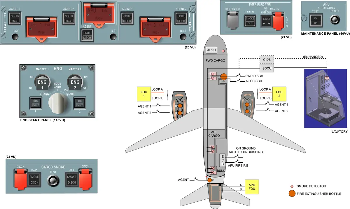
Airbus A320 Fire Protection Systems have:
- Fire detection and extinguishing systems for the engines and APU,
- Smoke detection for the avionics equipment and compartment,
- Smoke detection and fire extinguishing for the cargo compartments and lavatories,
- Portable fire extinguishers for the flight compartment and the cabin.
ENGINE
- 2 detection loops (A and B) – for each engine.
- Each fire detection loop contains 3 detector elements connected in parallel. (CEO)
- CEO – Fan, Core, Pylon
- NEO – Fan, Core, Pylon, AGB
- Monitored by FDU. (FDU 1 – ENG 1, FDU 2 – ENG 2)
- FDU has two channels capable of detecting any case of engine fire and loop failure.
- FDU > FWC
- Guarded ENG FIRE P/B – when released out,
- Cut off – fuel supply, hydraulic supply, electrical power, and bleed supply. The electric supply to the Engine Interface Unit (EIU) is also disconnected.
- Arms the extinguishing system.
- 2 fire bottles – pylon. (for each engine)
- with electrically operated squibs to discharge their agents.
- The SQUIB lights illuminate on the AGENT P/BSWs to indicate that AGENT P/BSWs can be used. – (Agent is now available to use).
- AGENT P/B – to discharge agents. (2 p/b for each engine).
- TEST buttons – for system tests (for both detection & extinguishing systems).
FIRE DETECTION LOGIC
Fire detection logic is the same for the engine and APU.
- In NORMAL STATE, the INTEGRITY switch is closed and the ALARM switch is open.
- In ALARM STATE: The effect of an average temperature expands the helium (inert) gas, which in turn closes the ALARM switch, or the effect of heat caused by a flame or hot gas, releases core (active) gas from the hybrid core, which in turn closes the ALARM switch. In both cases, the detector sends a fire signal.
- In FAULT STATE: In the event of gas pressure loss (pipe fracture or cut off due to a torching flame), the INTEGRITY switch opens and generates a fault signal.
The FDU generates a fire warning signal if any of the following conditions are met:
- Fire on loop A and fire on loop B,
- Fire on loop A and fault on loop B,
- Fault on loop A and fire on loop B,
- Fault on loop A and fault on loop B within 5 seconds (both loops broken due to a torching flame).
Loop Fault Warning
FDU generates an inoperative signal if any of the following conditions are met:
- Electrical failure
- Integrity failure
- detection of a single loop FIRE during more than 16s while the other loop is in normal condition.
ENGINE FIRE PROCEDURE
When a fire is detected, the Continuous Repetitive Chime (CRC) sounds, the MASTER Warning flashes, the ENGINE FIRE P/BSW light comes on and the FIRE light on the Engine panel comes on. The warning is shown on the Engine and Warning Display and the engine system page comes up automatically.
To follow the fire procedure the following actions have to be done:
- The Master Warning P/BSW may be pressed to cancel the continuous repetitive chime.
- set thrust lever to “IDLE”.
- set ENG MASTER 2 lever to “OFF”. When the MASTER lever is set to OFF, the low pressure and the high pressure fuel valves close and cause engine shutdown.
- release ENG 2 FIRE P/BSW. When the ENGINE FIRE P/BSW is released out the Single Chime (SC) sounds. The MASTER CAUTion comes on due to systems deactivation. The fuel low pressure valve closure is confirmed. The SQUIB lights illuminate on the AGENT P/BSWs to indicate that AGENT P/BSWs can be used.
To extinguish the fire the following actions have to be done:
- wait for 10 seconds: this is required to reduce engine windmilling, reducing the nacelle ventilation which increases the agent effect,
- press AGENT 1 P/BSW. When the AGENT 1 P/BSW is pressed, the fire bottle one is discharged in the engine compartment and the DISCHarge light comes on. If the fire still persists after 30 seconds, the second bottle must be discharged,
- press AGENT 2 P/BSW. When the fire is extinguished, the ENGINE FIRE P/BSW light and the FIRE indication on the ENG panel go off.
APU
- 2 detection loops (A and B) – mounted in parallel.
- Each APU fire detection loop is a single detector element installed.
- Monitored by Apu FDU.
- Apu FDU > FWC
- Guarded APU FIRE P/B – when released out,
- Cut off – electrical power and bleed supply.
- APU is immediately shut down (apu fuel supply cut-off)
- Arms the extinguishing system.
- 1 fire bottle for APU.
- with electrically-operated squibs to discharge their agents.
- AGENT P/B – to discharge agent.
- TEST buttons – for system tests.
- On the ground, an APU FIRE P/B will trigger an APU auto-extinguishing system shutdown and discharge the bottle automatically.
- The auto-extinguishing system can be tested through the maintenance test panel.
- In case of an APU FIRE on the ground –
- warning horn in the nose wheel well
- an APU FIRE indicator light on the external power panel.
- APU SHUT OFF switch on EXT PWR panel –
- Red disc is connected to an overpressure discharge tube.
AVIONICS COMPARTMENT
- Avionics SMOKE detector is installed in the air extraction duct. — only one.
- The detector is monitored by the AEVC.
- AEVC > FWC
- Indication –
- On the EMER ELEC PWR panel, the SMOKE light comes on in the GEN 1 LINE P/B switch.
- On the VENTILATION panel, the FAULT light comes on in both BLOWER and EXTRACT P/B switches.
- Action –
- Pilot action is required as part of the AVIONICS SMOKE procedure in flight – display on EWD
- As smoke is confirmed, the crew has to use the oxygen masks.
- To prevent smoke from entering into the cockpit and cabin, Cabin fans – OFF.
- BLOWER p/b switch and EXTRACT p/b switch – set to OVRD. This causes the blower fan to stop, opens the conditioned-air inlet valve and air is extracted overboard through the auxiliary flap inside the Skin Air Outlet Valve, which is partially open. The extract fan keeps on running.
- Cockpit crew should allow 5 minutes for the SMOKE warning to disappear.
- As smoke is still perceptible, it is necessary to act on the electrical system. Action will be shown on EWD.
- Isolate GEN 1 – GEN 1 LINE P/BSW – OFF
- GEN 1 disconnected (GLC 1 open), AC Bus 1 will be now supplied by GEN 2 through BTC (usually in auto position).
- Both side #1 pump will keep supplying. – taken upstream of GLC1.
- Deploy RAT – to keep the aircraft essential electrical network supplied.
- Now isolate GEN 2 also – GEN 2 P/BSW – OFF
- Isolate GEN 1 – GEN 1 LINE P/BSW – OFF
- As both engine generators have been disconnected, the electrical system is now in emergency configuration and the lower ECAM display is no longer supplied. The aircraft has to land as soon as possible by following the emergency procedure. The avionics smoke procedure is then completed.
CARGO COMPARTMENT
- Smoke Detectors > Cavity – Each cavity holds 2 smoke detectors.
- 2 Smoke Detectors – FWD Cargo (1 Cavity)
- 4 Smoke Detectors – AFT Cargo (2 Cavity)
- Smoke detectors are monitored by CIDS-SDF.
- Smoke Detection Function (SDF) is integrated in the CIDS.
- CIDS > FWC
- 1 Bottle – Discharged through,
- FWD – one nozzle
- AFT – two nozzle
- with electrically-operated squibs to discharge their agents.
- Standard system includes one extinguishing bottle. An optional system includes two bottles. The second bottle is required for extended range operations.
- When cargo smoke is detected, following activated warnings are:
- CRC,
- ASTER WARN light,
- ECAM message,
- SMOKE light on the CARGO SMOKE panel.
- In case of cargo smoke warning on ground you should never discharge the on-board extinguishing bottle. A visual inspection of the cargo compartment must be done. If fire is confirmed, portable extinguishers must be used.
LAVATORY
- 1 smoke detector – each LAV (in air extraction duct)
- Smoke detectors are monitored by CIDS-SDF.
- Smoke Detection Function (SDF) is integrated in the CIDS.
- CIDS > FWC
- Each lavatory waste bin has an automatic fire extinguishing system.
- A small pressurized extinguisher will automatically discharge if there is a fire. The fusible material in the discharge tube melts at high temperature and the pressurized agent is discharged into the waste bin.
- The lavatory smoke detectors are connected to type B Decoder/Encoder Units (DEUs) are linked to the CIDS-SDF.
When smoke is detected in a lavatory, Following cabin warnings:
- A triple chime is broadcast in all cabin or attendant station loudspeakers, — through DEU A, because passenger function is involved.
- A flashing amber light on the related Area Call Panel (ACP),
- “SMOKE LAV X” message is displayed and a red indicator flashes on all the Attendant Indication Panels (AIPs),
- SMOKE DETECTION page appears automatically on the Flight Attendant Panel (FAP) on which “SMOKE DETECTED” red message is displayed and a red icon is displayed at the affected location,
- the affected amber lavatory call light flashes.
- Simultaneously, the SDF 1 or 2 sends a smoke alert to the Flight Warning Computers (FWCs), which generates the following cockpit warnings:
- a Continuous Repetitive Chime (CRC),
- red MASTER WARNing light,
- LAVATORY SMOKE warning message on the EWD.
- If smoke is no longer detected, the directors automatically reset all visual and aural indications.
CABIN
- Portable fire extinguishers in the cockpit and cabin.
- Quantity, type and location – depends on interior configuration.
BITE
- FDU1, FDU2, FDU APU, AEVC, CIDS-SDF >> CFDIU >> MCDU
PRECAUTION
- The cartridge is an explosive device. To prevent explosion of the cartridge, install the applicable protective device. This will protect the electrical connector of the cartridge.
- When cartridge electrical connectors are disconnected, the cartridge electrical pins must be shunted with a protective shunt which is given by the manufacturer. A shunt plug or shorting clip will prevent bottle discharge which could cause injury to maintenance personnel.
- When installing engine or APU fire detection elements, be careful not to bend or damage the element.
- The engine and APU fire extinguishing bottles are connected to a HOT BUS. Make sure to pull all applicable C/Bs when doing maintenance on these systems, even without electrical power supplied to the aircraft.
FIRE TEST
During the engine FIRE test:
- FIRE light on overhead panel illuminates,
- FIRE light on engine start panel illuminates,
- both SQUIB lights illuminate,
- both DISCH lights illuminate,
- both red MASTER WARNING lights illuminate on the glare shield panel,
- continuous chime sounds,
- engine FIRE procedure displayed on upper ECAM DU,
- ENGINE page displayed on lower ECAM DU.
During the APU FIRE test:
- FIRE light on overhead panel illuminates,
- SQUIB light illuminates,
- DISCH light illuminates,
- both red MASTER WARNING lights illuminate on the glare shield panel,
- continuous chime sounds,
- APU FIRE procedure displayed on upper ECAM DU,
- APU page displayed on lower ECAM DU.
COMPUTERS
- ENGINE FDU 1 & 2
- APU FDU
See the location of A320 Computers.