A320 ATA 29 Technical Notes are brief and to-the-point information about the Airbus A320 hydraulic Power, including its components and their functions. ATA Chapter 29 deals with aircraft hydraulic power which includes systems used to store and deliver hydraulic fluids under pressure to their users.
A320 HYDRAULIC SYSTEM
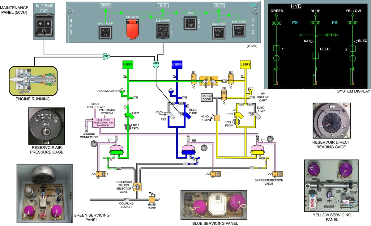
The Airbus A320 aircraft has three main hydraulic systems, identified as the Green, Blue, and Yellow. They generate hydraulic power at 3000 psi to the main power users such as the flight controls, landing gear, cargo doors, brakes, and thrust reversers.
Systems that are not used during flight, such as the cargo doors, brakes, landing gear, and nosewheel steering, are isolated from the main supply.
All three systems are not hydraulically connected, so hydraulic fluid cannot be transferred from one system to the other. Only power can be transferred using PTU.
USERS
- GREEN – Normal Brake, L/G, TR1, Flaps, Slats, Yaw Damper 1.
- YELLOW – Alternate Brake, NWS, Cargo Doors, TR2, Flaps, Yaw Damper 2.
- BLUE – CSM/G, Slats.
MAIN SYSTEMS
- GREEN – Pressurized by HYD Pump > connected to LH engine. ……. EDP1
- YELLOW – Pressurized by HYD Pump > connected to RH engine. ……. EDP2
- BLUE – Pressurized by E-Pump > ON automatically when any engine operates.
- Normal system operating pressure is 3000 PSI
- 2500 PSI when powered by the RAT (CSM/G).
- Hydraulic fluid cannot be transferred from one system to another.
- Power can be transferred using PTU.
AUXILIARY SYSTEMS
- RAT of Blue system,
- PTU Green/Yellow system,
- Electric and hand pumps Yellow system.
SYSTEM NUMBERING
- No. 1 system – Green
- No. 2 system – Blue
- No. 3 system – Yellow
- 123 – GBY
GROUND USE ONLY
- Blue E-Pump – Override p/b switch for ground use only
- Yellow E-Pump – only operates when engines are stopped. P/B or Cargo Door Selector – ON.
- Yellow Sys Hand Pump – only for cargo door operations.
- PTU can be used on ground to pressurized Green System using Yellow Electric Pump.
- Blue and yellow electric pumps are interchangeable.
HYDRAULIC COMPONENTS
Location of hydraulic components:
- GREEN – Main Landing Gear
- BLUE – LH side belly fairing > FWD of MLG
- YELLOW – RH side belly fairing > FWD of MLG
- Service Panels are AFT of MLG
- BLUE & GREEN – LH side belly fairing
- YELLOW – RH side belly fairing
- Reservoir Filling – LH side belly fairing
- Yellow Hand Pump – LH side belly fairing
- Handle – RH side belly fairing
- Ground connections – LH side belly fairing
MANIFOLDS
- Manifolds make it possible to install different components on the manifold.
- Replacement of components is possible with minimum effect on other components or pipes.
- GREEN – HP Manifold, LP Manifold, PTU Manifold
- YELLOW – HP Manifold, LP Manifold, PTU Manifold, Brake Manifold
- BLUE – HP Manifold only
PRIORITY VALVES
- In the event of low hydraulic pressure, the priority valves maintain the operation of essential systems by cutting off hydraulic power to heavy load users.
- It makes sure that all available hydraulic pressure is sent to the primary flight controls if pressure in the system is reduced.
- The threshold of the priority valve is 1842 psi.
- GREEN – priority valve is installed on the PTU manifold.
- YELLOW – priority valve is installed on the PTU manifold.
- BLUE – priority valve is installed on the HP manifold.
- The priority valve has three modes of operation:
- Full system pressure, the valve is open and fluid goes from port A (inlet) to port B (outlet),
- System pressure low, the valve is closed and fluid cannot get from port A to port B,
- More pressure downstream of the valve (at port B) than in the main system. The valve lets fluid flow from port B to port A.
- Priority valve is a kind of sequence valve.
LEAK MEASUREMENT VALVES
- The return flow of a hydraulic system is equal to the user’s demand flow plus the permanent internal leakage. The flight controls users are permanently supplied through leak measurement valves. These valves are electrically powered to the closed position for leak measurement test.
- Each system has a leak measurement valve upstream of the primary flight controls.
- Measure the leakage in each circuit. (Green, Yellow, and Blue circuits).
- Can be closed by p/b switches on the maintenance panel.
- Installed in the HP manifold of the respective system.
RESERVOIR PRESSURIZATION UNIT
- Reservoirs are pressurized by air at 50 psi to prevent cavitation.
- Reservoir Pressurization Unit for the pressurization of the reservoirs.
- Normally, HP bleed air from engine 1 pressurizes the hydraulic reservoirs automatically.
- Higher line pressure than crossbleed duct (65psi).
- 65 PSI > Pressure Reducing v/v > 50 PSI
- If the bleed air pressure is too low, the system takes bleed air pressure from the crossbleed duct.
- Low air pressure warning at < 22 psi.
- 2 water drain valves – 1 automatic, 1 manual.
- The Reservoir can be pressurized using a ground connection in the Reservoir Pressurization Unit.
- The non-return valves are in each reservoir supply manifold. >> Pressure maintained –
- for up to 12 hours after engine shutdown on ground, and
- for up to 3 hours after a failure of the air supply in flight.
ACCUMULATOR
- Capacity – 1.1 L
- Maintain a constant pressure by covering transient demands during normal operation.
- Precharged with nitrogen to 1885 psi at 20°C.
FIRE SHUT-OFF VALVE
- in the GREEN and YELLOW system only.
- installed upstream of EDP to isolate the system.
PTU
- A bidirectional power transfer unit enables the yellow system to pressurize the green system and vice versa.
- PTU = Pump <> Motor
- Electrohydraulic valves – 2, (for green & yellow) — controls the operation.
- Green <> Yellow
- Run automatically – when pressure difference > 500 PSI
- PTU inhibited when –
- PTU b/p OFF
- During cargo door operation
- One engine running, and
- Parking brake is ON, or
- NWS pin installed.
- PTU functioning is kept inhibited after cargo door operation for 40 sec.
- PTU 6 sec. logic in flight – within 6 sec other system has to build pr.
FILTERS
- HP filter – in pressure line of G/Y/B SYS
- + Reservoir filling system
- + Normal braking system
- LP filter – in return line line of G/Y/B SYS
- Case Drain filter – in case drain line of both EDPs.
- + blue electric pump
- Yellow E-Pump does not have a case drain line because it’s not a continuous running pump.
SEAL DRAIN
- Hydraulic fluid that may escape from some hydraulic components in the form of leak or abnormal condition is drained into collector tanks.
- Collector tank: 0.75 L
- FWD collector tank – Yellow hyd compartment
- AFT collector tank – MLG compartment
GREEN SYSTEM CONSUMERS
- Direct from the EDP (upstream of the priority valve):
- LH (No. 1) engine thrust reverser.
- From the HP manifold
- LH and RH spoiler 1 & 5
- LH and RH aileron
- LH and RH slat WTB
- RH flap WTB
- LH elevator
- Rudder
- THS
- Yaw damper
- From the PTU manifold (downstream of the priority valve):
- PTU
- RH slat power control unit (PCU) motor
- LH flap PCU motor
- nose landing gear and doors
- main landing gear and doors.
- From the PTU manifold (upstream of the priority valve):
- normal braking system.
YELLOW SYSTEM CONSUMERS
- Direct from the EDP/electric pump/ground supply,
- RH (No. 2) engine thrust reverser
- From the HP manifold
- LH and RH spoiler 2,
- LH and RH spoiler 4,
- LH flap WTB,
- RH elevator,
- Rudder,
- THS,
- Yaw damper.
- From the HP manifold
- FWD and AFT cargo doors,
- Brake manifold,
- Nosewheel steering.
- From the brake manifold,
- Alternate and parking brakes.
- From the PTU manifold (downstream of the priority valve)
- PTU,
- RH motor of flap PCU.
BLUE SYSTEM CONSUMERS
- From the HP manifold, downstream of the priority valve:
- LH slat PCU motor
- CSM/G.
- From the HP manifold, upstream of the priority valve:
- LH & RH spoiler 3
- LH & RH ailerons
- LH & RH slat WTB
- LH & RH flap WTB
- LH & RH elevators
- Rudder
- From the HP manifold, upstream of priority valve:
- RAT
CONTROLS AND INDICATIONS
OTHER POINTS
- There is no cooling system in hydraulic systems. In case of overheat, ON the pumps for recirculation.
- Hydraulic servicing panel – there is No Bypass filter, if popout – change the filter, no hydraulic will be uplifted.
- Locking tool for depressurization valve – for prolonged maintenance.
- Sometimes we see hydraulic fluid indication on ECAM is more than the limit – fluid expanded due to high temperature.
- HYD SYS – Phosphate eater base
- L/G – Mineral base
- Case drain filter – do not reset; open filter to check.
- White tag – ECAM indication
- Blue tag – ??
- There are no computers in ATA 29 of A320.
Tips to Remember Hydraulic Supply:
Spoilers – GYBYG (Remember GYB).
Yaw Damper – The top one is Blue (think of the sky), the bottom one is Green (think of the earth), and the remaining middle one is Yellow.
Tip: Many components on the LH side receive supply from the Green System because the Green System’s EDP is connected to Engine No. 1. Similarly, many RH side components are supplied by the Yellow System because the Yellow System’s EDP is connected to Engine No. 2. For example, the Elevator receives supply as follows: LH side from the Green and Blue Systems; RH side from the Yellow and Blue Systems. LH T/R from Green and RH T/R from Yellow.