A320 ECAM HYD PAGE
Reference Aircraft: A320neo/LEAP-1A26
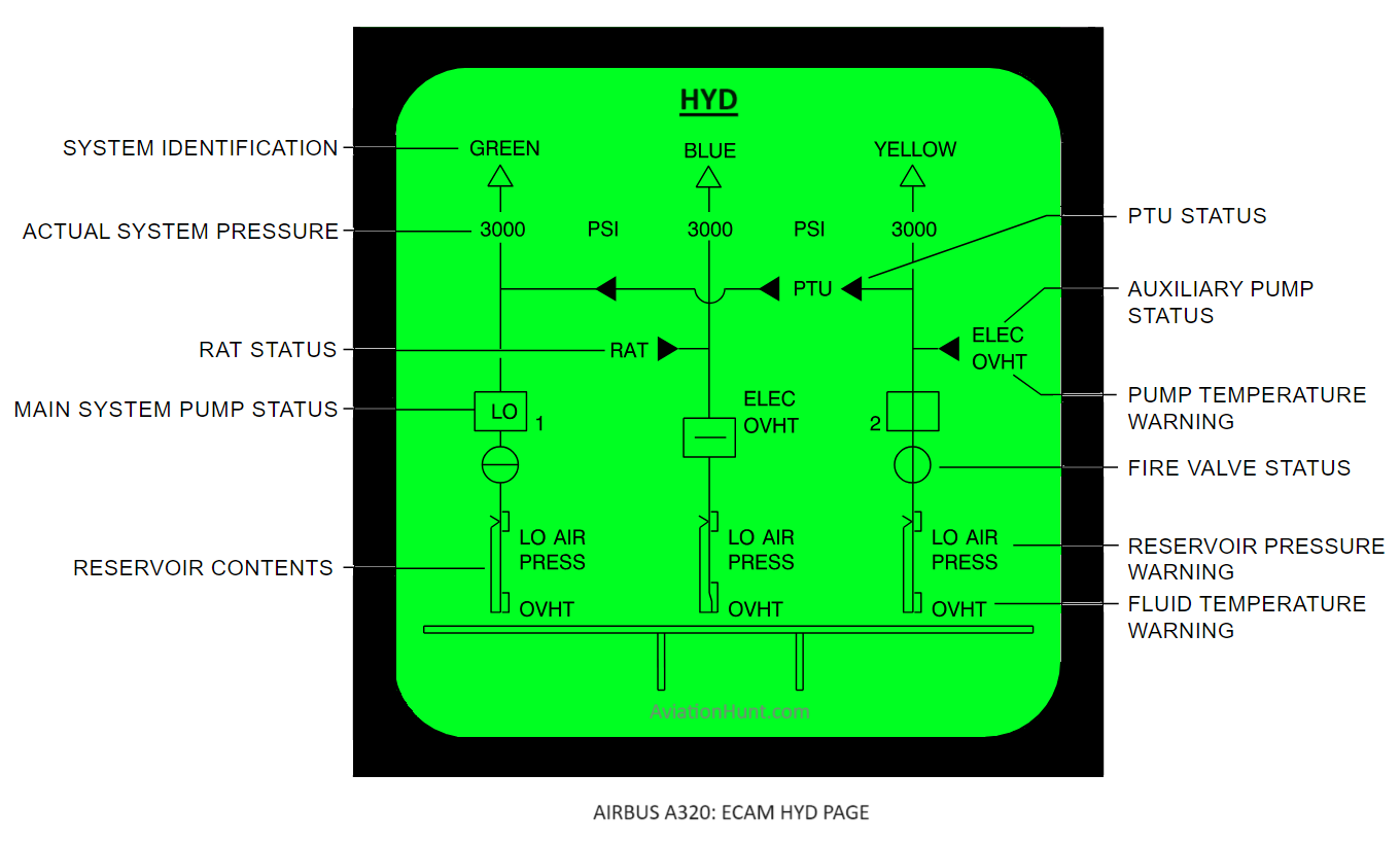
The A320 ECAM HYD page with its parameters is described in the image above as follows:
Hydraulic system status
- GREEN / BLUE / YELLOW is normally displayed in white with the arrow displayed in green.
- This is also the case when the low pressure status from the FWC, and also the pressure value from the SDAC, are transmitted as invalid.
- GREEN and the arrow are displayed in amber in case of hydraulic low pressure.
Hydraulic pressure
- The value of the related pressure is normally displayed in green.
- The pressure is displayed in amber when its value is below 1450 psi.
- The pressure is set to 0 psi and displayed in amber when its value is below 100 psi.
- The pressure is replaced by amber XX when its value is not available from the SDAC.
Yellow electrical pump
- The triangle is displayed in green when the yellow elec pump is on, and there is no low pressure.
- The triangle is displayed in white (outline only) when the yellow elec pump is off.
- The triangle is displayed in amber when the yellow elec pump is on and the pressure is below 1450 psi.
- The triangle is replaced by amber XX when the yellow elec pump status is not available from the SDAC.
ELEC indication
- ELEC is normally displayed in white, it is also displayed in white when the AC BUS 2 and the DC BUS 2 status are not available from the SDAC.
- It is displayed in amber when the AC BUS 2 is OFF or when the DC BUS 2 is OFF.
OVHT indication
- OVHT is displayed in amber when there is an ELEC pump overheat as transmitted by the SDAC.
- It is not displayed when there is no overheat or when the information is not available from the SDAC.
ENG pump (Yellow / Green)
- The pump is normally displayed running and green.
- The pump is displayed not running and amber when the pump is off.
- The pump status is replaced by LO when the pump is on and there is a low pressure.
- The pump is replaced by amber XX when the pump status is not available from the SDAC.
Fire valve (Yellow / Green)
- The valve is normally displayed open and green.It is displayed closed and amber when the fire valve is fully closed.
- It is replaced by amber XX when the valve status is not available from the SDAC.
Reservoir Level
- Index: A movable index represents the fluid level. The index is normally displayed in green. It is displayed in amber when the fluid level is below 3.5 litre. It is replaced by amber XX when the fluid level is not available from the SDAC.
- Low level area
- The low level area is displayed in amber.
- The low level limit is 3.5 litres for the yellow and the green reservoir.
- The low level limit is 2.4 litres for the blue reservoir.
- Normal filling level
- Yellow reservoir: The normal filling level is 11.2 liters inside a margin of 2.5 liters. It is displayed in green.
- Green reservoir: The normal filling level is 13.2 liters inside a margin of 2.5 liters. It is displayed in green.
- Blue reservoir: The normal filling level is 5.7 liters inside a margin of 1.5 liters. It is displayed in green.
- Fluid level scale: The fluid level is normally displayed in white. It is displayed in amber when the related index is amber.
- Maximum fluid level
- Yellow reservoir: The maximum level is 15.625 liter
- Blue reservoir: The maximum level is 8.125 liter
- Green reservoir: The maximum level is 18.125 liter
- LO AIR PRESS indication: This indication is displayed in amber when there is a reservoir low air press transmitted by the SDAC. Nothing is displayed when there is no low press or when the information is not available from the SDAC.
- OVHT indication: This indication is displayed in amber when the temperature of the reservoir is higher than 92°C. Nothing is displayed when the temperature is lower than 88°C or when the temperature value is not available from the SDAC.
BLUE ELEC Pump
- The pump is normally displayed in green when the pump is not OFF and when there is no LO PRESS.
- The pump is displayed in amber when it is OFF.
- The pump is replaced by an amber LO when the pump is ON and there is a LO PRESS.
- The pump is replaced by amber XX in all the other cases.
RAT link to the BLUE system
- The link is displayed in green when the RAT is not fully stowed.
- The triangle is white when the RAT is fully stowed with no residual pressure in the retraction jack.
- The triangle is amber when there is a residual pressure in the retraction jack.
- The triangle is replaced by amber XX when the RAT status is not available from the SDAC.
Hydraulic links
- Link to the green hydraulic system: This link is normally displayed in green. It is displayed in amber when the green pressure is lower than 1450 psi. When the pressure is not available from the SDAC the link is green.
- Link to the blue hydraulic system: This link is normally displayed in green. It is displayed in amber when the blue pressure is lower than 1450 psi. When the pressure is not available from the SDAC the link is green.
- Link from the PTU to the green system:
- This link is normally displayed in green, directed toward the green system (outline only) when all the following cases are not valid.
- It is displayed in amber, directed toward the green system (outline only) when there is a PTU fault (transmitted by the FWC), or when the PTU valve is commanded OFF.
- It is displayed in green, directed toward the green system (plain) when there is a green engine pump low pressure.
- It is displayed in amber, directed toward the green system (plain) when there is a green engine pump low pressure together with a PTU fault.
- It is displayed in green, directed toward the yellow system (plain) when there is a yellow engine pump low pressure.
- It is displayed in amber, directed toward the yellow system (plain) when there is a yellow engine pump low pressure together with a PTU fault.
- Link to the yellow hydraulic system: This link is normally displayed in green. It is displayed in amber when the yellow pressure is below 1450 psi as transmitted by the SDAC.
- Link from the ELEC pump to the yellow system: This link is normally displayed in green. It is displayed in amber when the yellow pressure is lower than 1450 psi or when a yellow engine pump low pressure occurs, the yellow ELEC pump being OFF. It is not displayed when the yellow system data are not available from the SDAC.
- Link from the yellow engine pump to the ELEC pump: This link is normally displayed in green. It is displayed in amber when a yellow engine pump low pressure occurs. It is not displayed when the information is not available from the SDAC.
- Link from the fire valve to the engine pump: This link is normally displayed in green. It is displayed in amber when the fire valve is displayed in amber or when the yellow reservoir quantity is lower than 3.5 liter.
- Link from the blue ELEC pump to the RAT: This link is normally displayed in green. It is displayed in amber when a blue ELEC pump low pressure occurs. It is not displayed when the information is not available from the SDAC.
- Link from the fire valve to the engine pump: This link is normally displayed in green. It is displayed in amber when the fire valve is displayed in amber or when the green reservoir quantity is lower than 3.5 liter.
- Link from the green ENG pump to the green hydraulic system: This link is normally displayed in green. It is displayed in amber when a green ENG pump low pressure occurs. It is not displayed when the information is not available from the SDAC.