The A320 ATA 32 Technical Notes provide brief and to-the-point information about the Airbus A320 Landing Gears, including its components and their functions.
A320 LANDING GEAR
The Airbus A320 Landing Gears support the aircraft on the ground and are oleo-pneumatic shock absorbers that absorb taxi and landing loads. During flight, the L/G is retracted into the landing gear bays in the belly of the aircraft. When the L/G is extended or retracted the related doors close to make the aerodynamic contours of the aircraft.
Main Landing Gear and Doors
- Each MLG has a MLG leg which includes an oleo-pneumatic shock absorber.
- A two-piece side stay assembly holds the MLG in the extended position.
- A lock stay keeps the side stay assembly stable in the lock down position.
- The lock stay provides an over center stop and a geometric lock of the L/G.
- a retraction actuator
- electrical and hydraulic dressings
- a torque-link damper
- a torque-link
- two lock springs,
- MLG legs have twin wheels, each wheel has a multi-disc brake unit.
- Three doors close each MLG bay. These are:
- a hydraulically-operated main door
- a mechanically-operated hinged door
- a fairing door on the MLG leg.
- A door opening mechanism lets the main door be opened on the ground for access to the MLG bay.
- A ground door-opening handle operates a bypass valve in the doors hydraulic circuit and releases the doors uplocks.
Nose Landing Gear and Doors
- NLG includes an oleo-pneumatic shock absorber and retracts forward into a bay in the fuselage.
- A two-piece drag strut assembly with a lock stay locks the leg in the extended position.
- The lock stay assembly provides an over centered stop and a geometric lock of the nose gear.
- The leg includes a hydraulically-operated steering mechanism.
- A gear actuating cylinder.
- NLG legs have twin wheels.
- Four doors and a fairing close the NLG bay. These are:
- two hydraulically-operated forward doors
- two mechanically-operated rear doors
- a fixed fairing on the NLG leg.
- A door opening mechanism lets the forward doors be opened on the ground for access to the NLG bay.
- A ground door-opening handle operates a bypass valve in the doors hydraulic circuit and releases the doors uplocks.
Extension and Retraction
- Free fall extension system
- Normal extension and retraction system
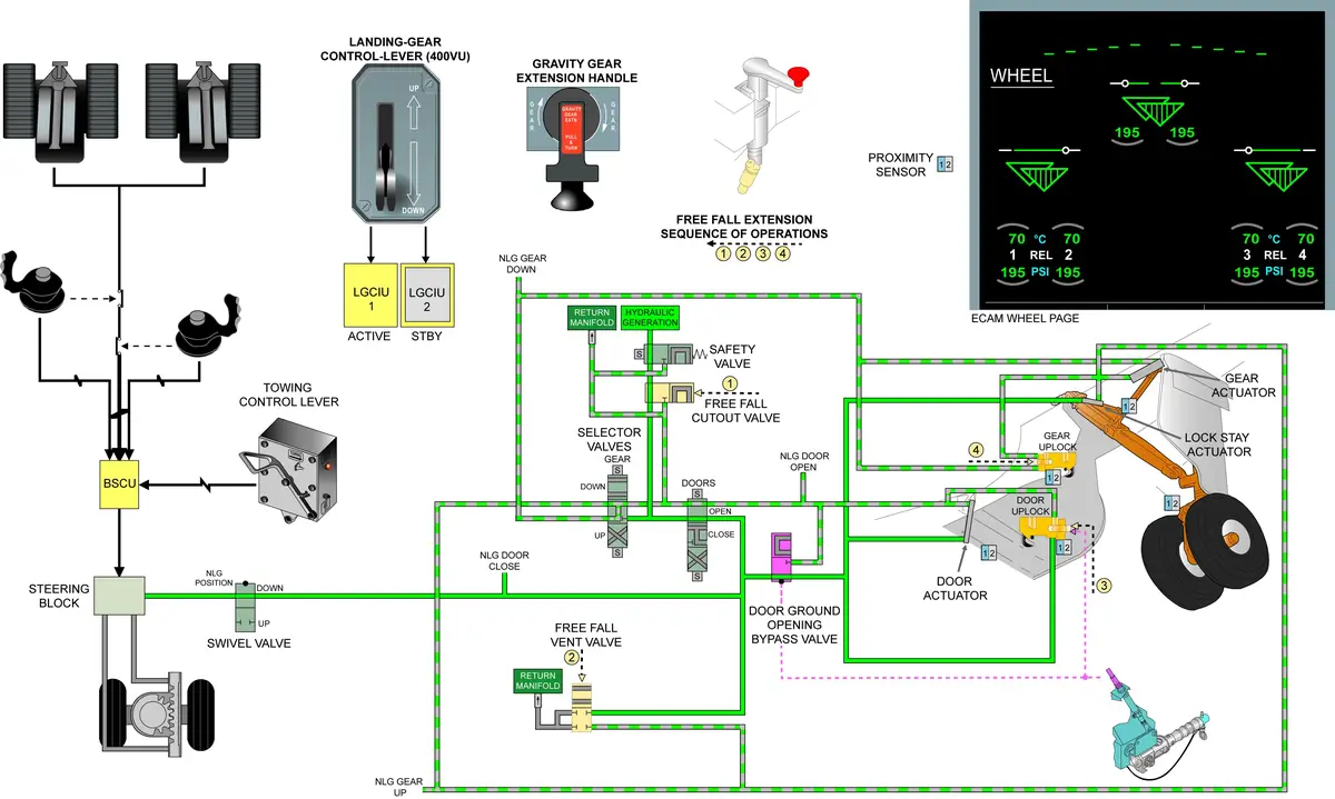
Normal extension and retraction system
- The system is electrically controlled and hydraulically operated.
- The hydraulic circuit has actuators that extend and retract the gears and open and close the doors.
- The L/G doors and the L/G have uplocks that lock the components in the retracted position. Geometric (overcenter) downlocks lock the L/G in the extended position.
- During MLG retraction, the hydraulic fluid retracts the piston which opens the over centered lock, to fold the side stay and the lock stay against the lock springs.
- The lock stay provides an over center stop and a geometric lock of the L/G.
- An anti-retraction baulk in the L/G control lever prevents an UP selection when:
- all three L/G shock absorbers are not fully extended (weight off the ground)
- the nose wheels are not in the center position.
- The green hydraulic system supplies the hydraulic power to operate the actuators.
- The system has two electro-hydraulic valves (selector valves) that control the operation of the actuators. One electro-hydraulic valve (Gear Selector Valve) controls the actuators for the L/G. The other (Door Selector Valve) controls the actuators for the doors.
- The LGCIU makes the selections of the valve assembly to retract or extend the L/G and move the doors in a given sequence.
- System has two independently electrical systems that control the operation of the hydraulic components. —- SYSTEM1 & SYSTEM2.
- The electrical control system has:
- a L/G control-lever
- two Landing Gear Control and Interface Units (LGCIU)
- a gear electro-hydraulic selector valve
- a door electro-hydraulic selector valve
- a L/G electro-hydraulic safety valve
- 32 proximity sensors and their related targets
- a set of indicator lights
- The electrical control system has two sub-systems, SYSTEM 1 and SYSTEM 2 which operate independently of one another. Each sub-system has:
- an LGCIU
- 16 proximity sensors (and their related targets)
- isolated electrical supplies
- SYSTEM 1 gets electrical power from Essential busbar
- SYSTEM 2 gets electrical power from the Normal busbar
- The primary hydro-mechanical components in the normal extension and retraction system are:
- 3 L/G actuating cylinders
- 3 door actuating cylinders
- 3 gear uplocks
- 3 door uplocks
- 3 door by-pass valves (door ground opening function)
- 1 NLG downlock release actuator
- 2 MLG lockstay actuating cylinders
SAFETY VALVE
- The safety valve is an electrically-operated, two-position valve that isolates the Green hydraulic supply to the L/G system. When airspeed is more than 264 kts the safety valve closes (solenoid de-energized). The safety valve opens (solenoid energized) when the airspeed is less than 260 kts and the L/G control-lever is selected DOWN. A safety valve connected to the ADIRS – for speed data.
- Safety valve – will not allow to open/extend the door/landing gear at high speed, it will break the components.
LGCIU
- control the operation of the landing gear (L/G) and doors.
- process proximity sensor and microswitch inputs from the Cargo Door Control System. The logic of the LGCIU processes all these signals to give an output signal.
- The two LGCIUs are interchangeable, but the aircraft wiring in SYSTEM NO 1 is different to that of SYSTEM NO 2.
- The aircraft can operate satisfactorily when one of the LGCIUs does not operate. When this occurs, the serviceable unit must be installed in SYSTEM NO.1
- One LGCIU controls one complete gear cycle, then switches over automatically to the other LGCIU at the completion of the retraction cycle. It also switches over in case of failure.
- LGCIU 1 – only > landing gear indicator panel.
L/G Door Ground-opening
- By-pass valves – door ground opening function.
- Each by-pass valve has three hydraulic connections marked A, B and C.
L/G door ground-opening
- When the ground door-opening handle is operated, it pulls a teleflex cable which moves the lever on the bypass valve through 90 degrees. The initial movement of the ground door-opening handle causes the bypass valve to:
- isolate the door-close hydraulic supply from the door actuating-cylinder
- connect the two chambers of the MLG door actuating-cylinder together.
- At the same time, the hook of the door uplock is released. Gravity then opens the main door, which causes the hydraulic fluid to move from one side of the door actuating-cylinder to the other. The main door opens slowly because some cavitation occurs in the door actuating-cylinder.
L/G door ground-closing
- The Green hydraulic system must be pressurized before the ground door-opening handle can be moved. A locking plunger in the bypass valve stops movement of the handle, if the hydraulic system is not pressurized.
- When the ground door-opening handle is turned towards the closed position, it pushes the teleflex cable. This moves the lever of the bypass valve. The valve then isolates the chambers of the main door actuator from each other and connects them to the hydraulic supply. At the same time, the rod to the uplock moves the ground release mechanism in the door uplock to its initial position. The main door actuator then closes the main door, and the uplock closes to hold the door actuating-cylinder in the closed position.
Free fall extension system
- extends the MLG and NLG if the normal extension and retraction system is not available.
- The system includes electrical rotary-type actuators.
- The actuators operate mechanical linkages to open the gear and door uplocks and hydraulic valves (vent v/v and cut-out v/v).
- When the uplocks release, gravity extends the L/G doors and the L/G. Springs (downlock springs) pull the downlock-links of the L/G into the locked position and the L/G doors stay open.
- Locking springs help the crew to crank the main gear into the locked condition, and aerodynamic forces assist in the locking of the nose gear.
- Free-fall extension-handle is at the rear of the cockpit center pedestal.
- To put the landing gear down by gravity, the flight crew must pull the gear crank out, then turn it clockwise for 3 turns.
- A system of rods, cables and bellcranks connect the free-fall extension-handle to:
- L/G door uplocks
- L/G uplocks
- vent valves
- a cut-out valve
- When the free-fall extension-handle is turned it operates the L/G components in the sequence that follows:
- the cut-out valve closes to isolate the pressure supply and connect it to return.
- the vent valves operate to bypass the normal L/G extension system.
- the L/G and the L/G door uplocks release.
- There are two mechanically-operated vent valves. one for the MLG and one for the NLG. The vent valve lets the hydraulic fluid move between the extension and retraction lines on some components, to prevent cavitation. It also lets any unwanted fluid go back to the reservoir through the third port on the vent valve. The third port on the vent valve connects to the Green hydraulic system return. Each vent valve has three hydraulic-port connections identified A, B and C.
- The mechanically operated cut-out valve isolates the L/G hydraulic system from the Green hydraulic system supply and connects the L/G selector manifold to the hydraulic reservoir return. The valve has three hydraulic-port connections identified A, B and C.
- Nose landing gear “ground” or “flight” information is given according to the shock absorber and wheel position. Nose Wheel (N/W) is automatically centered when the shock absorber is fully extended.
- Whenever gravity extension – OPS procedure must be followed.
Wheels
- The wheels are of aluminum alloy and can have a tubeless radial or bias ply tire.
Brakes
- Normal braking system
- Used to decrease the speed of the aircraft when it moves on the ground.
- Brake and Steering Control Unit (BSCU) controls the operation of normal braking.
- Each brake has two hydraulically operated pistons.
- When braking is necessary, hydraulic pressure is supplied from the Green main hydraulic system.
- The system has two modes of operation, manual and automatic, and gives automatic anti-skid protection in each mode.
- The input signals from the brake pedals are proportional to the amount of pedal travel and supply braking independently to each MLG.
- For automatic braking – 3 Pushbutton Switches (P/BSW) – each set an automatic braking program (LO, MED or MAX) in the BSCU, which gives a different deceleration rate. Use of the pedals that supplies an input signal more than a specified value, cancels an automatic braking program.
- The BSCU uses the input signals to make output signals which control the operation of the electro-hydraulic valves.
- If the normal braking system is not available, control automatically changes to one of the alternate braking systems.
- Alternate braking with anti-skid
- Alternate braking without Anti-skid
- Alternate braking system
- Parking brake system
- It is used to prevent movement of the aircraft when it is parked.
- It can also be used to stop the aircraft if all other braking systems are not available.
- The system operates from the accumulators in the alternate braking system.
- Brake Temperature System
- The brake temperature system includes a temperature sensor at each brake which measures the temperature and sends the data to a brake temperature monitoring unit. The brake temperatures are shown automatically on the wheel page of the ECAM System Display (SD)
- Brake Cooling System
- manually controlled system that decreases the temperature of the brakes when they are too hot.
- The system includes a P/BSW and an electrically operated fan in each MLG wheel.
- Touchdown protection for brake
- Anti-skid
- Break will not apply when the pilot press the pedal.
- Normal break – more than 1000 psi and can go up to 3000 psi, depends on deceleration rate.
- Alternante brake pr. limited to 1000 psi without antiskid function.
- In case of Emergency – parking brake ON/OFF ON/OFF ….
- 14 piston – 7 normal + 7 alternate
- SV – 4 – per brake – current is directly proportional to valve opening.
- DDV – 2 – per leg – combined pressure for both wheels in one leg.
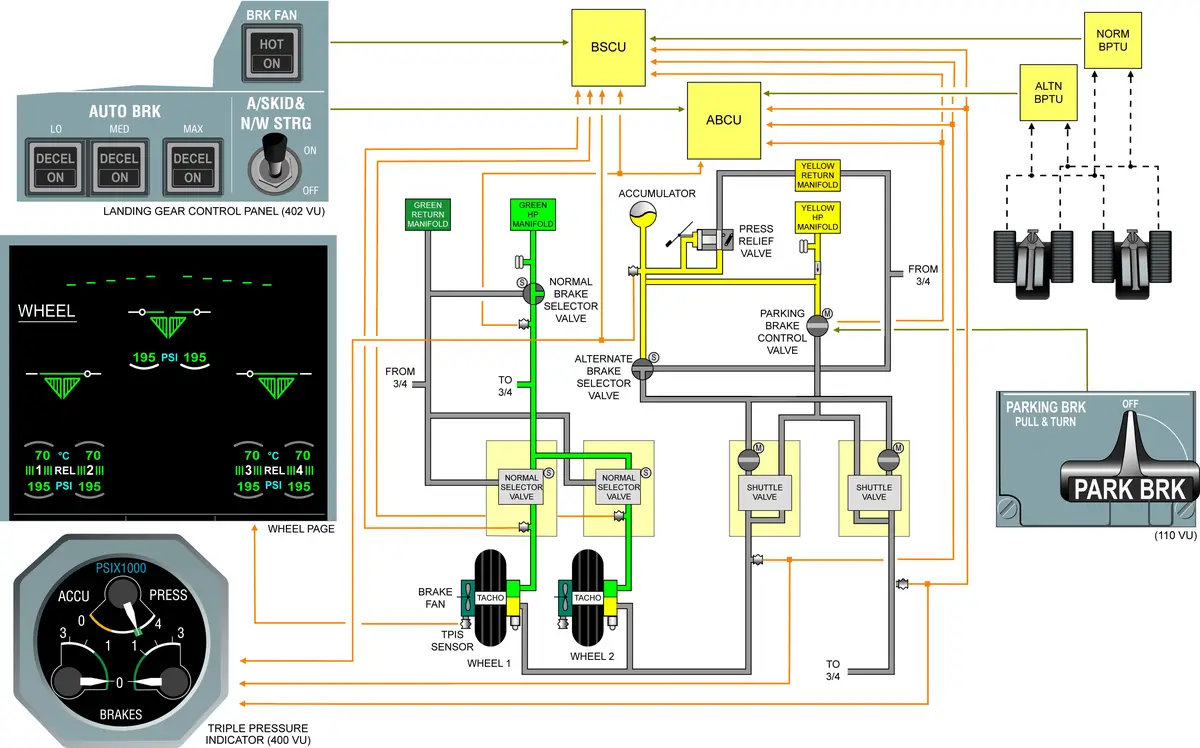
Steering
- The steering system changes the direction of the aircraft when it moves on the ground.
- The steering system is controlled by the BSCU.
- The system uses the Yellow main hydraulic-power system.
- Two handwheel transmitters in the cockpit supply the primary steering inputs to the BSCU.
- The rudder pedals and the autopilot supply secondary input to the BSCU through the flight control computers.
- Simy dampening function – inside the nose steering actuator
COMPUTERS
- LGCIU
- BSCU
- BTMU
CONTROLS AND INDICATIONS
Key Points
- Statement for brake set – Parking brake set, pressure holding.
- Brake temp – BTMU
- Internal accumulator in Hydraulic Block for steering – so that we can do towing in cold a/c.
- Brake binding – Brake release fault message on ECAM (need to release the brake)
- Piston is stuck, brake is not released.
- Jack and rotate.
- L/G safety devices – PINS – Top to bottom.
- Brake pedal – during bleeding – if more rapidly – fuse will activate.
- If tachometer is inop – autobrake will not be available.
- Temp vs Pr. graph – check AMM. Placard on MLG/NLG just for reference.
- If the wheel is hot – approach wheel at 45 degree angle.
- Over inflation – 105 %
- Under inflation – 90 %
- Wheel max operating speed – 225 km/hr.
- Normal brake – yellow pump > ON > PTU > AUTO (ON) > Green Sys Pressurized.
- Antiskid s/w- ON
- If OFF – brake sys will go to alternate mode.
- Antiskid s/w – is for BSCU
- L/G door – yellow pump > PTU > green sys
- L/G indication
- Upper half – UNLK – red – L/G not in selected position
- Lower half – triangle – green – down & locked
- Normal – uplocked – no light
- BSCU
- Channel 1 & channel 2
- Standby will take control when the L/G control lever is placed in down position.
- So, BSCU switching is when L/G lever is selected in the down position.
- BSCU channel changeover – NWS & Antiskid s/w – OFF then ON
- If brake is hot – apply water only on tyre not on brake/wheel. >> Otherwise – thermal stress and inflight ice formation due low temp.
- On SD wheel page – indication on – left side – by LGCIU 1 / right side – by LGCIU 2 (?)
- If brake leaks – stains may be on tyre (check it)
- Torque link – front
- Slave link – aft – for wire routing
- LGCIU 2 – MEL > only for 7 flight cycle
- Parking Brake – 2 motor
- Supply from battery
- Supply from normal power