A320 ECAM WHEEL PAGE
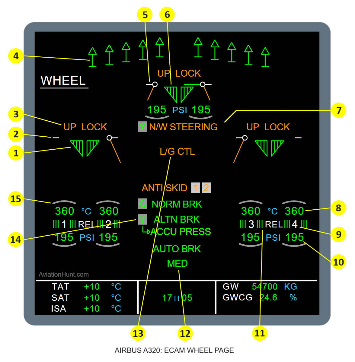
The A320 ECAM WHEEL page with its parameters is described in the image above as follows:
- 1: L/G position
- 2: L/G door operation
- 3: UP LOCK message
- 4: Spoilers position indication
- 5: Nose L/G doors operation
- 6: Nose L/G operation
- 7: NOSE WHEEL STEERING Message
- 8: Brake temperature
- 9: Wheel number
- 10: Tire pressure indication (optional)
- 11: Brake release
- 12: Braking Messages
- 13: L/G CTL Message
- 14: Hydraulic status
- 15: Hottest brake indication
Reference Aircraft: A320neo/LEAP-1A26
1. L/G position
- The left symbol is related to Landing Gear Control and Interface Unit 1 (LGCIU1) and the right symbol to LGCIU2.
- The landing gear is green (fully colored) when the corresponding gear is downlocked and not uplocked.
- The landing gear is red (fully colored) when the corresponding gear is not uplocked and not downlocked.
- The landing gear is not displayed when the corresponding gear is uplocked and not downlocked.
- The left symbol changes to amber XX when the signals from LGCIU1 to the Display Management Computer (DMC) are not correct.
- The right symbol changes to amber XX when the signals from LGCIU2 to the DMC are not correct.
2. L/G door operation
- Door closed and green: The door is uplocked and the door is not fully open.
- Door ajar and amber: The door is neither uplocked nor fully open.
- Door open and amber: The door is fully open and not locked up.
- Amber XX: The door is replaced by amber XX when the door position is not available from the LGCIU1 (left part), or from the LGCIU2 (right part).
3. UP LOCK message
- This message is displayed in amber when the gear uplock is engaged with the gear downlocked.
- It is not displayed in the other cases or when no valid data are available from either LGCIU.
4. Spoiler status indication
- The spoiler is represented out and green, when the spoiler status is transmitted correctly from the FCDC bus, the spoiler is extended and available, also from the FCDC bus.
- The spoiler is represented in and green, when the spoiler status is transmitted correctly from the FCDC bus, the spoiler is retracted and available, also from the FCDC bus.
- The spoiler is represented out and amber when the spoiler status is transmitted correctly from the FCDC bus, the spoiler is extended and faulty (hydraulic failure or servo loop failure), as transmitted from the FCDC bus.
- The spoiler is represented in and amber when the spoiler status is transmitted correctly from the FCDC bus, the spoiler is retracted and faulty, as transmitted from the FCDC bus.
- The spoiler is replaced by amber XX when the spoiler status is transmitted as not valid from the FCDC bus, or the information is not transmitted correctly from the FCDC bus.
5. Nose L/G doors operation
- Doors closed and green: The door are uplocked and not fully open.
- Doors ajar and amber: The doors are neither uplocked nor fully open.
- Doors open and amber: The doors are fully open and not locked up.
- Amber XX: The doors are replaced by amber XXXX when the doors positions are not available from neither LGCIU.
6. Nose L/G position
- The symbol is green when the NLG is locked down and not locked up.
- The symbol is red when the NLG is not locked up and not locked down.
- The symbol is not shown when the NLG is not locked down and is locked up.
- The left symbol changes to amber XX when the signals from Landing Gear Control and Interface Unit 1 (LGCIU1) to the Display Management Computer (DMC) are not correct.
- The right symbol changes to amber XX when the signals from LGCIU2 to the DMC are not correct.
7. NOSE WHEEL STEERING Message
This message, normally not displayed, is displayed in amber when:
- The nose wheel steering is inoperative as transmitted by the SDAC, or
- The ANTI SKID is OFF as transmitted by the SDAC, or
- Both BSCU channels are faulty as transmitted by the SDAC, or
- The Yellow hydraulic circuit is low pressure.
8. Brake temperature
- The digits for the brake temperature value are normally displayed in green (from 0 to 995°C by step of 5°C).
- They are displayed in amber when an over heat occurs on the corresponding brake as transmitted by the SDAC. They remain displayed in green when the overheat signal is not transmitted correctly.
- The value is replaced by amber XX when transmitted as not valid by the SDAC.
9. Wheel number
- The wheel number is displayed in white. Only the brake release changes (ref. below).
10. Tire pressure indication (optional)
- Normally, the pressure of the related wheel is shown in green, but when the pressure is low, it is shown in amber.
- When the System Data Acquisition Concentrator (SDAC) does not transmit the low pressure information correctly, the amber XX indication is shown.
- The value can change from 0 psi (0 bar) to 255 psi (17.58 bar) in increments of 5 psi (0.34 bar).
11. Brake release
- When the brake of the related wheel is released, as transmitted by the SDAC, the small symbol featuring the brakes next to the white REL indication is displayed in green in normal operation on each individual wheel.
- In amber on each individual wheel if there is a brake released fault, or
- In amber for all wheels in same time in case of:
- Loss of the ALTN BRK function on the left or right wheels, AND
- Loss of the NORM breaking function, or
- Loss of both BSCU, or
- ANTI SKID is fault and nose wheel steering capability installed, or
- ANTI SKID is selected OFF, or
- Yellow and Green hydraulic system is low pressure.
- It is not displayed when the brake is not released or when information is not transmitted correctly by the SDAC.
12. Normal and Alternate Braking Messages
ANTI SKID Message:
- This message, normally not displayed, is displayed in green when:
- The message NORM BRK is displayed in amber,
- Or the message ALTN BRK is displayed in amber,
- Or the message AUTO BRK is displayed in amber.
- This message is displayed in amber when:
- The anti skid switch is OFF,
- Or both BSCU channels are faulty as transmitted by the SDAC,
- Or the message NORM BRK is displayed in amber and the pressure of the yellow hydraulic circuit is low.
System 1/2 related to ANTI SKID status
- At the same time as the ANTI SKID message, the status of the BSCU system 1 is displayed:
- Normally displayed in green
- The figure is displayed in amber when the BSCU system 1 is faulty.
- The figure is surrounded by a half grey box.
- Likewise the system 2 is displayed.
NORM BRK Message
- This message, normally not displayed, is displayed in green when:
- The message ALTN BRK is displayed in amber,
- Or the message AUTO BRK is displayed in amber.
- This message is displayed amber when:
- The anti skid switch is OFF as transmitted by the SDAC
- Or both BSCU channels are faulty as transmitted by the SDAC
- Or the normal brake system is faulty,
- Or the GREEN hydraulic circuit pressure is low.
ALTN BRK Message
- This message, normally not displayed, is displayed in green when:
- The alternate braking mode is ON
- and neither the GREEN nor the YELLOW hydraulic pressure are low
- And the anti skid switch is not OFF
- And neither BSCU channel is faulty as transmitted by the SDAC
- Or the message NORM BRK is displayed in amber,
- Or the message AUTO BRK is displayed in amber.
- The message is displayed in amber when:
- There is an alternate braking left and right release fault,
- Or the YELLOW pressure and the YELLOW accumulator pressure are low,
ACCU PRESS Message
- ACCU PRESS message is displayed in green when:
- NORM BRK, or ALTN BRK, or AUTO BRK, or ANTI SKID is displayed in amber,
- Together with a YELLOW hydraulic low pressure.
- Or when yellow hydraulic circuit is low pressure.
- ACCU PRESS is displayed in amber when:
- The YELLOW accumulator undergoes a low pressure
- ACCU ONLY is displayed in green when:
- The YELLOW hydraulic circuit undergoes a low pressure, and the NORMAL brake mode is faulty (NORM BRK in amber)
- Or the YELLOW hydraulic circuit undergoes a low pressure.
Arrow indication
- This arrow is always displayed in green, when an ACCU message is displayed, whatever the message (ACCU PRESS or ACCU ONLY), and whatever the color:
- The arrow shows the YELLOW hydraulic circuit supplying the accumulator, when the YELLOW hydraulic circuit does not undergo a low pressure.
- The arrow shows the YELLOW accumulator supplying the alternate braking mode, when the YELLOW hydraulic circuit undergoes a low pressure.
AUTO BRK Message
- This message is displayed in amber when:
- At least two SEC ground spoiler are faulty or invalid, or
- When the auto break is faulty, or
- When both BSCU command or monitor are faulty, or
- When ANTI SKID is OFF or when ANTI SKID is fault and nose wheel steering capability installed.
- The message is green and flashing for 10s when the auto brake mode is OFF.
- The message is green when a decelerating mode is armed.
- The message is not displayed in all other cases.
LOW, MED, MAX decelerating mode message:
- LOW is displayed in green when the low decelerating mode is engaged.
- MED is displayed in green when the medium decelerating mode is engaged.
- MAX is displayed in green when the maximum decelerating mode is engaged.
- These messages are not displayed when one decelerating mode is not valid or no decelerating mode is engaged.
13. L/G CTL Message
- This message is displayed in amber,
- when the gear lever selector is in the UP position as transmitted by the LGCIU1, or 2 and the nose gear, the main right gear, or the main left gear are not UP, or
- the gear lever selector is in the DOWN position as transmitted by the LGCIU1, or 2 and the nose gear, the main right gear, or the main left gear are not DOWN.
14. Hydraulic status
- The hydraulic supply indications are displayed at the same time as the message N/W STEERING, or the message NORM BRK, or the message ALTN BRK.
- Y refer to the YELLOW hydraulic status, while G refer to the GREEN hydraulic status. The letter, normally displayed in green, is displayed in amber in case of low pressure. The hydraulic status is not displayed when not transmitted as valid by the SDAC.
15. Hottest Brake indication
- A green arc is displayed on the hottest wheel when the related temperature is higher than 100°C and there is no overheat on the brake.
- The arc is displayed in amber when there is an overheat.
- The same arc is displayed in grey when the related wheel is not the hottest wheel and in all other cases.