The A320 ATA 49 Technical Notes are brief and to-the-point information about the Airbus A320 Auxiliary Power System, including its components and their functions. ATA Chapter 49 deals with Airborne Auxiliary Power.
Auxiliary Power System
The Auxiliary Power System serves a crucial role in the aircraft’s operations. It enables the aircraft to function independently of electric and pneumatic ground power, thereby facilitating ground operations. This means that the aircraft can power itself up autonomously, which is particularly useful when servicing at airports that lack sufficient ground power facilities.
Furthermore, the auxiliary power system is available during flight, allowing the aircraft to operate under MEL conditions and ETOPS.
The system’s power source, the gas turbine engine (the APU), is designed to provide 115VAC for the operation of the aircraft’s electrical systems. It also supplies pneumatic power to let main engine start (MES) and environmental control system (ECS) operations.
The A320 APU
The APU for the Airbus A320 aircraft is the 131-9(A) model, and it is supplied by the AlliedSignal Aerospace Company – Engines division.
The APU’s power plant is installed in the rear fuselage aft of the passenger compartment. It occupies the tailcone, the rearmost portion of the fuselage. The tailcone has been fitted with a fireproof compartment to house the APU.
The APU engine primarily comprises a power section that produces shaft power. A load compressor is flanged to this shaft to generate pneumatic power. The same shaft also drives a gearbox. A generator is attached to this gearbox to generate electrical power.
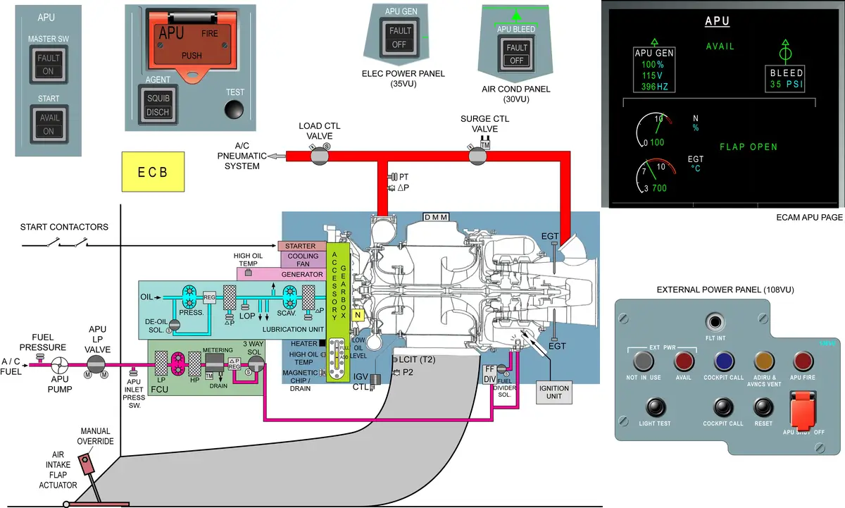
A320 APU Schematic
APU KEY POINTS
- APU Supply
- Electrical power for the A/C systems,
- Bleed air for engine starting and air conditioning on the ground,
- Bleed air for air conditioning/pressurization and wing anti-ice in flight.
- APU is designed to operate throughout the entire flight envelope.
- Electric power – available whenever the APU operates.
- Pneumatic power – available up to 20000 feet.
- APU is installed in the tail section of the fuselage.
- APU control and monitor by ECB (Electronic Control Box).
- ECB location – aft cargo compartment, right side.
- APU master switch, APU start switch – cockpit.
- Inlet
- Air intake flap – electrically operated
- Air intake duct
- Compressor
- Single-stage centrifugal compressor with a 7.5:1 pressure ratio
- Centrifugal compressor is less likely to suffer blade or disc failure than an axial flow compressor.
- Combustion chamber
- Reverse-flow annular combustion-chamber
- 1 igniter plug
- 10 fuel nozzles (flow divider > primary and/or secondary fuel manifold)
- Turbine – two-stage axial-flow turbine
- Exhaust – exhaust pipe
- Load compressor
- Single-stage centrifugal compressor with a compressor ratio of 4:1
- Inlet guide vanes (IGVs) are installed at the entrance of the compressor housing to control the compressor output to the aircraft pneumatic system.
- 16 IGVs are moved simultaneously by a gear train operated by an actuator.
- An APU load control valve and a surge control valve are installed on the outlet orifices of the bleed air T-duct.
- Load control valve (LCV) stops or permits the bleed air flow from the APU to the pneumatic system of the aircraft.
- APU load control valve and APU bleed valve are the same thing.
- LCV is a pneumatically actuated butterfly valve.
- Surge control valve (SCV) prevents a load compressor surge. The excess air passes through the valve to the exhaust cone.
- SCV is a hydraulically (Fuel Pressure) actuated butterfly valve.
- Accessory drive gearbox
- Starter motor
- AC generator
- Fuel control unit (FCU)
- Lubrication unit – wet-sump lubrication system
- Cooling air fan >> air > Oil cooler
- Fuel Feed System
- Fuel pump (115V AC, 400Hz, single phase),
- LP valve,
- APU inlet LP switch,
- Fuel drain and vent system.
- FUEL >> LH Crossfeed Duct >> Fuel Feed System > Fuel Control Unit
- Drain system
- Drain Tank – 1
- KISS Seal – 3
- Drain Mast
- Drain Tank > Drain Mast — Suction effect at 200 kts
CONTROLS AND INDICATIONS
- APU CONTROL PANEL
- AIR COND CONTROL PANEL (APU BLEED)
- ELECTRICAL CONTROL PANEL (APU GEN)
- FIRE CONTROL PANEL (APU FIRE)
- INDICATIONS ON ECAM APU SD PAGE