The aircraft fuel system stores and supplies fuel to the engines and the APU. Aviation fuel is used to convert into heat energy and then kinetic energy in the aero engine.
All aircraft powered by engines require fuel on board to operate the engines. The basic requirements of any fuel system are to provide a continuous flow of contaminated free fuel to the engines at a pressure and flow rate to sustain operations regardless of the attitude of the aircraft.
Let’s dive in to –
- Fuel storage
- Overwing Refueling
- Pressure Refueling
- Defueling / Draining
- Venting
- Engine fuel feed
- APU fuel feed
- Cross-feed System
- Fuel Jettison
- Fuel Lines and Fittings
- Fuel quantity indicating
- A320 Aircraft Fuel System
Aircraft Fuel System – from Storage to Engine Feeding and Indications
The Aircraft Fuel System is not a single system. It consists of various subsystems. The exact subsystem varies from aircraft to aircraft model or from different manufacturers, but the principle is the same. To understand the complete working of the fuel system of any aircraft, first, you need to understand the basic elements, components, and various small subsystems that contribute to the design of a complete fuel system.
If you are a student or mechanic you might have studied the basics of the fuel system for small aircraft. So I’m skipping the basic fuel system for small aircraft like removable fuel tanks and gravity feed system. If you have any doubts, ask in the comment box or join our Facebook community. Now let’s begin with fuel storage…
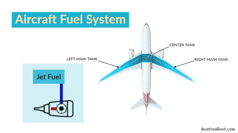
Fuel Storage
There needs to be some form of storing for the fuel prior to it being used by the aero engines. It is stored in fuel tanks near the aircraft’s longitudinal center of gravity in the wings and center fuselage.
There are three basic types of aircraft fuel tanks:
- rigid removable tanks,
- bladder tanks, and
- integral fuel tanks.
Let’s skip the rigid removable tanks and bladder tanks. Because modern air transport aircraft use integral tanks as their main fuel storage system.
Integral Fuel Tanks
Integral Fuel Tanks are used in the transport category and high-performance aircraft. It is a part of the structure of the wings or the fuselage.
Integral fuel tanks are unused spaces inside the wings. Aircraft with integral fuel tanks in the wings are called wet wings.
The advantages of integral tanks are that they are easily maintained, are cheap, and save weight.
These tanks have access panels for inspection and repairs of the tanks and other fuel system components. On large transport category aircraft, technicians need to physically enter the tank for maintenance.
When entering an integral fuel tank, all fuel must be emptied from the tank, and safety procedures must be followed.
Surge Tank
Surge tanks are empty tanks located in the wing outboard of the main wing tanks. These are used for fuel overflow. A check valve allows the one-way drainage of fuel back into the main tanks. Surge tanks also used for fuel system venting.
Additional Fuel Tank
Some aircraft models allow additional fuel tanks to be installed. These additional tanks, usually located in the fuselage section of the aircraft.
Overwing Refueling
This method of fueling an aircraft is similar to the way most motor cars are fueled on the garage forecourt. The biggest disadvantage during overwing refueling is that of time to refuel. Access to the tanks is difficult and requires step ladders, high rise platforms, etc and the actual filing process can be slow. Great care needs to be exercised when using this method of refueling to avoid spillage. Overwing refuel points are still fitted to many large aircraft, but they are rarely used.
Pressure Refueling
This is a system of refueling where fuel under pressure (max 50 psi) is supplied from a bowser, tanker, or refueling pumping vehicle. It is common at airports to have the fuel pumped underground. A vehicle connects to the ground connection after lifting a steel cover plate and pumps the fuel into the aircraft. The bowser’s (fuel tanker) fuel hose is connected to the refueling point. From this single point, there is a pipework system connected to all the tanks in the aircraft. The fuel is controlled into each tank by energizing solenoids in the refuel valves.
The benefit of single-point pressure refueling at a fueling station is, it is accessible by ramp refueling trucks which allows all aircraft fuel tanks to be filled with one connection of the fuel hose.
Advantages of pressure refueling include:
- Higher pressures and flow rates and shorter refueling times.
- Less risk of spillage.
- Ability to fill any tank with any desired quantity of fuel using the aircraft’s onboard refueling control system.
- Reduced risk of fuel contamination.
- Better access. Fueling points are accessed from the ground.
- Reduced the risk of fire.
Defueling / Draining
Sometimes, generally for maintenance, the fuel needs to be removed from the tanks. If personnel need to enter the tank for inspection purposes, there needs to be some means of draining that fuel away. Prior to entering a tank for any reason, the tank will need to be defueled and drained completely.
The only way fuel can be removed from a tank during a defuel operation. Even after a complete defuel, there are still puddles of unusable fuel left in the tanks and this has to be removed by draining. The drain ports are also used for taking fuel samples.
Venting
As fuel is pumped into or out of the tanks (refueling, defueling, engine use) air has to be allowed into and out of the tank. Failure to do so could cause the tanks to rupture during refueling operations or a vacuum to occur when the engines are running and thus starve them of fuel.
When allowing venting careful consideration has to be given as a highly explosive fuel/air mix is being moved from the tank/s to the outside atmosphere. Also when allowing air into the tanks contamination may enter via the venting system.
The purpose of the venting system is to:
- Balance the air pressure within the fuel tanks with ambient air.
- Allow for thermal expansion of the fuel/fuel-air mixture in the tanks.
- Protect the tanks from excessive internal pressures.
Engine Fuel Feed
There needs to be a system to feed fuel to the engines. Although engines will suck fuel using their own pumps, booster pumps are provided to ensure a positive flow.
The engine fuel feed system supplies fuel from the fuel tanks to the engines. A positive pressure is required to keep the fuel flow rate at an adequate level and to prevent cavitation in fuel lines and components. So a pump is installed in the line from the tanks to the engine. The engines use fuel from the center tank before the main tanks.
APU Fuel Feed
The APU fuel feed system supplies fuel to the APU. The APU usually receives fuel from main tank 1. However, with the use of the fuel boost pump switches, any fuel tank can supply fuel to the APU. Most aircraft have separate standby fuel pump for APU.
Cross-feed System
Fuel from the boost pumps is pumped out of the tanks and into the cross-feed manifold. It is controlled by a series of valves; to move fuel down to the engine the spar valve (also called LP valve) has to be opened, which is controlled by the engine fuel control. This valve is the last part of the airframe system. From here on the fuel system is considered to be part of the engine. To move fuel to another engine via the cross-feed manifold, one of the cross-feed valves is opened.
Fuel Jettison system
For most large aircraft it isn’t structurally possible to land an aircraft at its maximum all-up weight. Usually on long-distance flight aircraft will take-off heavier than they are allowed to land.
During the flight, fuel is burned and aircraft weight falls. If a serious malfunction causes a return to base just after take-off the pilot needs to dump some of the fuel overboard to reduce the weight of the aircraft. This is done using a fuel jettison system.
It is worth noting that due to environmental and cost concerns, aircraft do not often jettison fuel, they will usually opt for an overweight landing – with special checks to be carried out by the maintenance engineer afterward.
During maintenance, care needs to be exercised to prevent inadvertent discharge of fuel from the jettison nozzles. These jettison nozzles are often protected with air/ground sensing logic (weight switches or squat switches). The air/ground logic switch operated when the landing gear shock absorbers compress on landing. This means they cannot be opened with the aircraft on the ground unless CB’s for the air/ground logics are pulled.
Fuel Lines and Fittings
Aircraft fuel line fittings are usually either AN or MS fittings. Both flared and flareless fittings are used.
Aircraft fuel lines can be rigid or flexible depending on location and application. Rigid lines are often made of aluminum alloy and are connected with Army/Navy (AN) or military standard (MS) fittings. However, in areas like engine compartment and wheel wells, subject to damage from debris, abrasion, and heat, stainless steel lines are often used.
During leaks at fittings, technicians should not overtighten any leaky fitting. If the proper torque does not stop a leak, depressurize the line, disconnect the fitting and visually inspect it for a cause.
Fuel Quantity Indication
I’m not going to mention all older types of indicating system. Most aircraft now have capacitive type systems to indicate fuel quantity. So let’s begin with the operating principle of the capacitive type system.
If two metal plates are placed close together (but not touching) with a dielectric (this may be air or fuel – or any other material for that matter) in between, a capacitor is formed.
The value of a capacitor is given by the formula: C = εA/d
Where A is the surface area of the metal plates and d is the distance between them. These two values are fixed by the manufacturer of the unit. The value of ε (lowercase Greek letter epsilon) is altered by changing the dielectric constant, and that happens as the level of the fuel is changed. This is because fuel and air have different values of ε (permittivity).
Capacitive tank units are normally calibrated at the manufacturer end, so it doesn’t require on-wing calibration.
There is a need to compensate for the change in fuel density and there are a couple of ways of achieving this. The simplest form of the compensator is a small capacitive unit (called a compensator) that sits at the bottom of the tank, often close to the sump drain.
Unless the tank is completely drained it will always be totally immersed in fuel. This means that any change in capacitance of this unit is not due to a change in the fuel level, but due to a change in the density of the fuel. This signal is then used to trim the main tank units to allow for the slight changes in fuel relative density.
A320 Aircraft Fuel System
As an aircraft engineer (mechanic) I have worked mostly on A320 aircraft. Here I’m not going to describe the whole A320 aircraft fuel system, but yes I can give you some brief idea about the fuel system of A320 aircraft.
There is one fuel tank in each wing (divided into an inner and outer cell) and one in the center wing box. There are also two vent surge tanks. The vent surge tanks are located in each wing outboard of the wing tank.
Each vent surge tank vents to the atmosphere through a NACA type intake connected with a vent duct. Inside the vent duct, there is a vent protector and a flame arrestor. The function of the vent protector is to prevent clogging of the vent duct by ice formation. The flame arrestor reduces the risk of a ground fire igniting the fuel tanks. Fuel spilled through the vent pipes into the surge tank is induced back into the outer cell by a scavenge jet pump using motive power from the wing fuel pumps.
Each wing tank inner and outer cell vents to the related vent surge tank. The vent lines are fitted with a vent float valve. Two vent float valves prevent fuel from passing in the vent lines during aircraft bank maneuvers.
The center tank vents into the LH vent surge tank.
Overpressure protectors are also installed in A320 to relieve pressure in the tanks that might occur through vent blockage or a pressure refueling gallery failure. See AMM system description, how overpressure protector relieves fuel to other tank or discharge overboard to protect the tank from rupture.
Total 8 water drain valve installed in A320 aircraft fuel tank.
- 3 in each wing (1 in inner cell, 1 in outer cell, 1 in vent surge tank) – Lower surface of the wing.
- 2 in center tank (LH & RH side) – Electric hydraulic pump compartments.
Each tank has two centrifugal booster pumps. All wing tank pumps are fitted with pressure relief sequence valves which ensure that, when all pumps are running, the center tank pumps will deliver fuel preferentially. When the center tank is empty, fuel is supplied from the wing inner cells. There is no direct feed from the outer cells to the engines.
Two inter-cell transfer valves are used to transfer fuel from the outer cells to the inner cells when the fuel quantity gets to the low level (about 750 kg). Each valve is operated by an electrical motor.
FQIC (Fuel Quantity Indication Computer) performs the fuel mass calculations. A320 has a capacitance type system to indicate fuel quantity. There are 5 probes in the center tank and 14 per wing tank.
In each tank inner cell, fuel probe No. 2 and in each outer cell fuel probe No. 13 have diodes that give the fuel temperature to the FQIC for indication on the ECAM system display.
In case of failure of the quantity indicating system, the fuel Manual-Magnetic Indicators (MMIs) must be used to monitor the quantity in the tanks. A320 is equipped with 4 Magnetic level indicators per wing and one per center tank.