A320 ATA 23 Technical Notes are brief and to-the-point information about the Airbus A320 Communication System, including its components and their functions. ATA Chapter 23 is titled Communications, which covers radio communications and on-board communications. This also includes data communications.
A320 Communication System
The Airbus A320 Communication System is mainly used for voice communications and can also be used for data communications if needed. This system allows communication between crew members and between crew and ground personnel. It is also used to communicate with passengers, other aircraft, and ground stations (both speech and data).
The communication system is used for speech communications and optionally for data communications.
The communications system comprises the following subsystems –
- VHF/HF System
- VHF Data Radio (VDR) system
- HF Data Radio (HFDR) system
- Radio tuning systems
- Radio Management Panels (RMPs)
- Audio integrating system
- Audio Management Unit (AMU)
- Audio Control Panels (ACPs)
Two types of communication systems –
- Radio Communication
- VHF System – VHF1, VHF2, VHF3
- HF System – HF1, HF2 (optional)
- On-board communication
- Flight Interphone – AMUs hosts the flight interphone.
- Cabin Interphone – CIDS hosts the cabin interphone.
- Passenger Address – CIDS hosts the PA.
- Service Interphone – CIDS hosts the service interphone. (on ground only).
- For data communication, optional VDR (VHF Data Radio) & HFDR (HF Data Radio) transceivers can be used. >> VHF Data Link / HF Data Link.
Learn the Basics: How do communication systems work on aircraft?
VHF SYSTEM
- VHF1, VHF2, VHF3
- VHF Data Radio (VDR) system
- VHF is used for all short-range voice communications between different aircraft in flight or between the aircraft and ground stations.
- Optionally, aircraft can have the VHF Data Link (VDL) system, to communicate via the data mode (data communication), in addition to the voice mode (voice communication).
- VHF3 is used as a back-up system.
- ATSU (ACARS) uses VHF3 for data transmission. – Data Communication.
- Main components : XCVR – 3 & ANTENNA – 3
- VHF system operates within the frequency range – 118 to 136.992 MHz with a 8.33 KHz spacing between the channels.
- In case of continuous emitting, the ECAM displays – COM: VHF 1/2 EMITTING.
- BITE is integrated in XCVR.
HF SYSTEM
- HF1, HF2
- HF Data Radio (HFDR) System
- HF are used when aircraft is beyond the useful range of VHF radios.
- HF system serves for all long-distance voice communications between different aircraft in flight or on the ground, or between the aircraft and one or several ground stations.
- Main components – XCVR-2, COUPLER-2, ANTENNA-1
- HF system operates within the frequency range – 2.8 to 23.999 MHz, with 1 KHz spacing between channels.
- HF antenna is mounted under the leading edge of the vertical stabilizer, the RF energy given out during transmissions can cause an explosion during refueling.
- DO NOT TRANSMIT during refueling.
- In case of continuous emitting for more than one minute, the ECAM displays in amber: COM: HF 1/2 EMITTING.
- BITE is integrated in XCVR.
ON-BOARD Communication System
Divided into 4 functions:
- Flight interphone for cockpit internal communication and communication with the ground mechanic, Control by AMU.
- Service interphone (on ground only) for maintenance technician communication with cockpit or cabin (for this, many jack connectors are installed around the A/C). – Control by CIDS. (Cockpit communication – via AMU, linked with CIDS).
- Passenger Address (PA) from the cockpit or from cabin crew stations for passenger announcements. – Control by CIDS.
- Cabin interphone for cabin crew or cabin crew/pilots communication. – Control by CIDS.
CDIS – Cabin Intercommunications Data System
For redundancy, the CIDS has two identical directors (DIRs). In normal operation, DIR 1 is active and DIR 2 is in hot stand-by. DIR 2 receives and computes the same data as DIR 1 but its outputs are disabled when director1 is available. The director commands cabin equipment via Decoder/Encoder Units (DEUs). The cargo smoke system is linked by Controller Area Network (CAN) buses. The Flight Attendant Panel (FAP) is linked by ethernet buses.
Each DIR is separated into two parts:
- DIR main functions with the integrated Vacuum System Control (VSC) function (VSCF),
- Smoke detection function (SDF).
CIDS Main Components
- Directors – 2 CIDS Directors – Controls many cabin functions. Directors are central control components in CIDS.
- Decoder/Encoder Units (DEUs) – are data interfaces for CIDS.
- DEU type A – for passenger function
- DEU type B – for cabin attendant function
- DEU A & DEU B – are not interchangeable. Normally we only replace DEU not the connection box – function code is inside the connection box.
- Flight Attendant Panel (FAP) – are the main user interface – to monitor and control the cabin systems. (FWD)
Integrated within the FAP – in flash card format
- CAM – Cabin Assignment Module
- CIDS configuration database is stored in CAM.
- OBRM – On Board Replaceable Module
- Storage device for system software (e.g. director, forward attendant panel).
- PRAM – Prerecorded Announcement and Music
- Announcements and the boarding music are stored on a compact flash card.
- I-PRAM CF-CARD – Integrated PRAM
FAP
- Display Unit – Touch Screen
- Sub-panel
- Hard Keys
- LIGHTS MAIN ON/OFF
- LAV MAINT
- SCREEN 30 sec LOCK
- EVAC CMD
- EVAC RESET
- SMOKE RESET
- Switch
- EMER (light)
- Interfaces
- USB plug
- Headphone plug
- Hard Keys
Other Components / interface
- Additional Attendant Panel (AAP) – to control certain cabin systems. (AFT)
- Attendant Indication Panel (AIP) – 3, shows dial and call information, 1 at each cabin crew station.
- Area Call Panel (ACP) – indicates:
- Crew calls (pink steady or flashing),
- Passenger call (blue steady),
- Lavatory call (amber steady),
- Lavatory smoke detection (amber flashing).
- Cockpit Handset (1) and Cabin Handsets (3, 1 at each cabin crew station).
- Passenger Interface and Supply Adapter (PISA) – PISA is the interface between the DEU type A and components of the Passenger Service Unit (PSU). The PISA has interfaces to the following equipment:
- Reading-light switches and reading lights
- Passenger call/reset pushbutton
- Passenger-call lights
- Seat row identifier
- Loudspeakers
- NS, FSB and RTS signs.
- Seat Belts & No Smoking ON/OFF from SIGNS PANEL in Cockpit.
- CIDS interface with SFCC – for auto seatbelt sign and no smoking sign, when both switches are in auto position.
CIDS controls many other cabin related functions like –
- Cabin Illumination
- Cabin Ready Signaling
- Emergency Evacuation Signaling (EVAC)
- Potable Water Indication on FAP
- Waste Indication on FAP
- Vacuum System Control Function (VSCF)
- Escape Slides Pressure Monitoring
- Emergency Power Supply Unit (EPSU)
- Drain Mast Control Unit (DMCU)
- CFDS Emulation on FAP
EVAC
The emergency evacuation command may be activated from the cockpit, from the purser station, and optionally from the Additional Attendant Panel (AAP).
EVAC panel in cockpit
- Toggle switch – to select who can give command >> CAPT & PURS / CAPT
- EVAC horn shut off button.
- EVAC Command p/b.
RADIO MANAGEMENT
- Radio Management Panel – RMP1, RMP2, RMP3
- RMPs enable a centralized frequency control of the VHF and HF radio communication equipment.
- The RMPs also enable the frequency control of the radio navigation equipment – in case of failure of the FMGC – standby navigation mode.
- VHF Omnidirectional Range (VOR),
- Distance Measuring Equipment (DME),
- Instrument Landing System (ILS),
- Automatic Direction Finder (ADF)
- If the standby navigation mode is selected, the navigation systems frequencies are controlled by RMP 1 and RMP 2 only.
- A RMP failure is indicated by the blanking of the display windows. If a failure occurs, the failed RMP has to be switched off. When selected off, the RMP sends a discrete signal for system reconfiguration.
- BITE of RMP – BITE function available through CFDS.
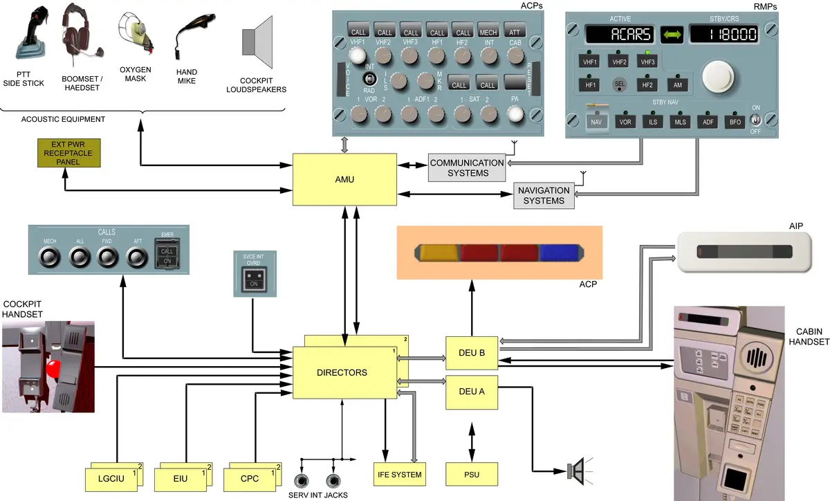
AUDIO MANAGEMENT
The Audio Management System (AMS) allows the flight crew to use all the radio communication and radio navigation facilities installed on the aircraft in transmission and reception mode. It also allows to use interphone systems, call systems, and passenger address system.
AMS Components
- 1 Audio Management Unit (AMU) – Ensures the interface between the user (jack and ACP) and various radio communication and radio navigation systems.
- Equipped with test circuit and connected to CFDIU – BITE Test.
- AMU has a decoding unit called SELective CALling (SELCAL).
- 3 Audio Control Panels (ACP) – ACP1, ACP2, ACP3
- ACP 1 – Captain
- ACP 2 – F/O
- ACP 3 – 3rd occupant.
- Three to five identical Audio Control Panels (ACPs) can be installed.
- Allow for audio channel selection for both transmission and reception.
- Display the various calls – SELCAL, Ground mechanic call, and calls from Cabin Attendants.
- 1 SELCAL Code Panel – is used to program SELCAL code assigned to the aircraft.
- Boomset Receptacle and Headset Jack – for CPTN, FO, plus 2 extra.
- Boomsets for CPTN, FO, plus 2 extra.
- Hand Mic – 2
- Cockpit oxygen mask microphone – 3
- Cockpit Loudspeaker Potentiometers (with incorporated switches) – 2
- Cockpit Loudspeakers are part of ATA 31 Central Warning System.
- Radio PTT Switches (on sidestick) – 2
- AUDIO SWITCHING Selector Switch – 48VU
- The AUDIO SWITCHING selector is used in case of communication failure on CAPT or F/O channels.
- The message “AUDIO 3 XFRD” is displayed in green on the ECAM MEMO display.
- 3rd occupant ACP – ACP 3 – can be used as CAPT or FO
Cockpit Loudspeaker Muting Circuit
- A muting circuit is installed to avoid acoustic coupling between the loudspeakers and the microphones. When a transmission is keyed by any push-to-talk switch, a ground signal is delivered to the two loudspeaker amplifiers. This ground signal decreases the gain and band-pass of the loudspeaker amplifiers.
- This attenuating circuit is not operative with the Flight Warning Computer (FWC) audio outputs.
SELCAL and CALL
- SELective CALling (SELCAL) and CALL functions are done in the Audio Management Unit (AMU) by the SELCAL/CALL card.
- This card receives SELCAL calls from the ground stations; calls from ground crew and cabin attendant stations and sends visual and aural warnings.
- calls from the ground stations – from ATC
- The ground system transmits, via VHF or HF transmitters, a selective call code. The aircraft receivers detect and capture the call signals transmitted by the ground stations (VHF or HF).
- calls from ground crew and cabin attendant stations – on A/C
- Ground Crew Call
- Cabin Attendant Call
- calls from the ground stations – from ATC
Selcal Operation
The SELCAL/CALL card has 7 inputs connected to the communication receiver SELCAL outputs. These inputs are permanently scanned, and when a SELCAL signal is present, a comparison is made with the code programmed on the SELCAL code panel. When the 2 codes agree, a message is sent to the various Audio Control Panels (ACPs), via the corresponding audio cards. On the ACPs, the CALL light, corresponding to the communication channel used, flashes amber. At the same time, data is sent to the Flight Warning Computers (FWCs). The FWCs send an audio call buzzer to the loudspeakers. The call is cancelled using the RESET key on one ACP, or selecting the called channel and activating the Push To Talk (PTT).
Ground Crew Call
When the cockpit call pushbutton, located on the external power control panel, is pressed, ground information is sent to the SELCAL/CALL card and to the FWC. The FWC activates the buzzer signal through the loudspeakers. The SELCAL card sends a signal through the various audio cards to the ACPs. The MECHanical legend flashes amber for 60 seconds on the ACPs. The visual call is automatically cancelled and the circuit reinitialized after 60 seconds or when the RESET pushbutton is pressed in, on any ACP. The automatic reset may be cancelled with the AMU pin programming.
Cabin Attendant Call
When a call is made from a cabin attendant station, the Cabin Intercommunication Data System (CIDS) generates ground information to the SELCAL/CALL card and to the FWC. During one second, the FWC activates the buzzer signal through the loudspeakers. The SELCAL/CALL card sends a signal through the various audio cards to the ACPs. The ATTendant legend flashes for 60 seconds on the ACPs. The visual call is automatically cancelled and the circuit reinitialized after 60 seconds or when the RESET pushbutton is pressed in, on any ACP. Information is also sent to the CIDS for re-initialization. The automatic reset may be cancelled with the AMU pin programming.
Flight Interphone System
- Control by AMU.
- Has two functions –
- Cockpit internal communication –
- Communication with ground crew – Ground Crew Call System
- Ground Crew Call System
- Enables crew member-to-ground mechanic or ground mechanic-to-crew member calls.
- The system operates on the ground only.
- A Mechanic Call HORN 15WC located in the nose gear well.
- CALLS/MECH P/B on CALLS PANEL 21VU
- COCKPIT CALL P/B, RESET P/B, and INDICATOR light – on External Power Panel 108VU.
- It has also an aural warning function when the aircraft is powered by batteries for the systems given below – (Sound comes from Horn (15WC))
- APU fire,
- ADIRS powered by batteries,
- Equipment ventilation faulty.
Service Interphone
- Activates only on ground – weight on wheels signals from LGCIU.
- Control by CIDS.
- Can communicate with the cockpit (via AMU, linked with CIDS) and cabin.
- Total 8 – servicing jacks.
- Service interphone override switch for maintenance purposes when a/c is on jack.
- When the switch is pressed – NO signals from LGCIU.
- Jack at the external power panel is not a servicing jack that is a flight interphone.
- Inflight, all jacks are isolated due to interference. If a/c is on jack – it will sense flight mode, for that override p/b is given on the maintenance panel.
CALLS Panel
- The CALL panel lets the cockpit crew gain the attention of a ground mechanic or the cabin crew by triggering visual and audio signals.
- For mechanic call the horn will sound, for cabin crew a high low chime will be broadcast on respective areas.
Static Discharger
- Static Dischargers are installed on the aircraft to protect the communication systems from interference caused by static electricity.
- Discharge the static electricity accumulated by the aircraft during its flight.
- Avoid static electricity discharging noise and ensure a good quality of radio transmission, without interference.
- CEO – Total 39 Static Dischargers
- NEO – Total 33 Static Dischargers
- Missing Allowed (See CDL for appropriate)
- Wingtip and aileron – 2 each wing / 9 per wing
- Horizontal stabilizer – 1 each side / 5 per side
- Fin and Rudder – 1 / 5
- Flap track fairing – 1 each wing / 3 per wing
Cockpit Door Surveillance System (CDSS)
- CDSS is installed to let the flight crew identify a person in front of the cockpit door and to survey the hidden cross section in the door number 1 area.
- Three “NTSC video format” black and white video cameras in the door number 1 area,
- CDSS has –
- 3 ANTI HIJACK CAMERA
- 1 LCD AND SYSTEM CONTROLLER
- 1 VIDEO SWITCH – on Cockpit Door Panel 119VU
- 1 COCKPIT DOOR VIDEO ON/OFF – on Cockpit Door Video Panel 27VU
Cockpit Voice Recorder (CVR)
- Regulatory requirements
- For FAA – 28 V DC power supply
- For EASA – 115 V AC power supply
- Power supply difference only.
- The cockpit voice recorder records the last 2 hours of the flight crew conversations and communications and aural warnings.
- NEO – records up to 25 hrs.
- It records automatically in flight and on ground when at least 1 engine is running and for 5 minutes after the last engine is shut down and also 5 minutes after aircraft energization.
- The CVR can be supplied manually. To do this, push the GND CTL P/B on the RCDR panel.
- CVR – 1
- CVR Control Panel
- CVR TEST P/BSW
- GND CTL P/BSW
- HOT MIC
- CVR ERASE P/BSW
- CVR Test – Two ways
- Test for captain – by test button
- Test for maintenance crew – by using separate test headset or ground headset on maintenance panel. Do not use a CAPT/FO headset because there is a difference of resistance.
- Prior to test, the CVR must be energized by pressing the GND CTL P/B with the engines not running.
- CVR Erase function – may be deactivated due to local regulatory requirements.
ELT SYSTEM
- The Emergency Locator Transmitter (ELT) function is to transmit distress signals. The ELT system transmits on 3 frequencies:
- 121.5 MHz (Civil) and
- 243 MHz (Military) homing-signals, and
- 406 MHz to the COSPAS-SARSAT satellite system.
- 243 MHz = double of 121.5 MHz.
- The battery-pack, installed in the ELT housing, supplies the power to operate the system.
- The ELT system includes these components:
- An ELT,
- An Aircraft Identification Module (AIM) – we do not change while replacing ELT.
- A Remote Control Panel (RCP) – panel in the cockpit.
- An antenna – top of aft galley,
- An indicator – led indicator on ELT
- A horn – 15WC – An emergency signal can be heard on the 121.5 MHz frequency, at the cockpit loudspeaker, during test.
- The signal transmission can continue for approximately fifty hours.
- The three-position switch controls three modes:
- OFF mode: there is no power available from the battery-pack and the ELT circuits are not energized. The ELT cannot detect a crash or transmit rescue signals. You cannot operate a BITE test in this mode.
- ARMED mode: the necessary circuits are energized and the ELT can detect a start signal from the G-switch, the RCP or the ELT ARM/OFF/TX switch. After the signal is received, the ELT switches to transmit mode. You can operate a BITE test in this mode. There are 3 different types of operation in the armed mode:
- Automatic operation occurs when the G-switch detects an impact sufficient to start the transmit mode,
- Manual operation occurs when you need to transmit a signal (aircraft out of operation, injured passengers/crew members), or when you do a BITE test,
- Accidental operation occurs when the ELT is connected to its system in the A/C and the G-switch starts transmission without a real emergency (hard landing).
- Transmit mode: the ELT starts to transmit 121.5/243 MHz and 406 MHz signals to the antenna.
- BITE test can be done with the RCP or the ELT.
- The ON indicator comes on when the ELT operates, or to give the BITE test result. During ELT transmission the indicator slowly flashes continuously.
- ESD Precaution – Wrist strap – Whenever use first check with tester.
COMPUTERS
- AMU – 1
- CIDS DIR – 2
- VHF Transceiver – 3
- HF Transceiver – 1 or 2
See the location of A320 Computers.