The A320 ATA 28 Technical Notes provide brief and to-the-point information about the Airbus A320 Fuel System, including its components and their functions. ATA Chapter 28 refers to the fuel system of an aircraft. This includes the storage, supply, and management of fuel for the engine, APU, and cooling.
A320 FUEL SYSTEM
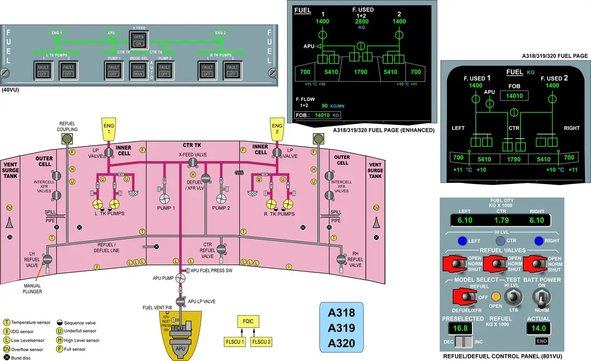
The Airbus A320 fuel system stores fuel in the main and center tanks, which are open to the atmosphere through vent surge tanks. The system controls and supplies the correct amount of fuel to these tanks during refueling operations. The fuel system supplies fuel for thrust to the engine. It also provides fuel to the auxiliary power unit (APU). Furthermore it –
- Circulates fuel to cool the Integrated Drive Generator (IDG).
- Keeps fuel in the outer tanks for wing bending and flutter relief.
Tip: Correct fuel specification – get from Flight Manual
STORAGE
- Wing tank – in each wing
- LH wing tank > outer cell > inner cell > collector cell
- RH wing tank > outer cell > inner cell > collector cell
- Fuel from outer cell to inner cell
- Two intercell transfer valves – controlled by FLSCU.
- Fuel in the wing tank outer cell is moved to the related inner cell by gravity when the related intercell transfer valve/s is/are open.
- v/v open when – fuel in inner cell < 750kg.
- v/v open automatically and are latched until the next refueling. – this trigger ecam memo “Fuel Auto XFR”. Both side LH & RH tank transfer valves open at the same time and also close at same time.
- Fuel from inner cell to collector cell
- Seven clack valves
- This makes sure that the main fuel pumps are always in fuel.
- Components in each collector cells –
- 2 Fuel pump canisters and their related fuel pump.
- 2 Fuel strainers
- 1 Suction valve – for gravity feeding if wing tank pumps fail.
- 2 Check valves – prevent reverse flow when pumps are off.
- Components in each outer cells
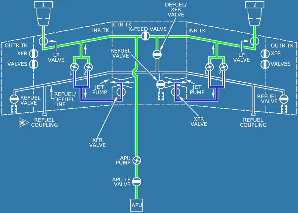
- Two scavenge jet pumps
- 1 – Remove fuel from vent surge tank to rear intercell transfer valve. A Check valve, in the line between the vent surge tank, combined with this jet pump, makes sure that fuel cannot enter the vent surge tank via the pump if the wing tank pumps are off.
- 2 – Mix fuel and water within the outer cell.
- Each scavenge jet pump receives its motive fuel pressure from the wing tank pumps, if running.
- Center tank – in center wing box
- Each tank is a part of the aircraft structure.
- After refueling, fuel can expand by 2% (20 deg.C temp rise) without spillage.
WATER DRAIN
- Water drain valves
- Fuel tanks are filled to a minimum of 10% of capacity – to cover drain v/v outlet.
- 3 in each wing – lower surface of the wing.
- 1 in inner cell,
- 1 in outer cell,
- 1 in vent surge tank
- 2 in center tank – electric hydraulic pump compartments.
- LH & RH
VENTING
- Each wing contains a vent surge tank for venting. – NACA type intake.
- Also, Vent surge tanks temporarily hold the fuel to prevent leakage.
- Vent surge tanks keep their related fuel tank open to the external air pressure.
- LH vent surge tank – for the LH wing tank and the center tank
- CTR TK vent line connected to LH vent surge tank.
- RH vent surge tank – for the RH wing tank
- LH vent surge tank – for the LH wing tank and the center tank
- Fuel tank venting system components:
- Flame arrestor – at vent intake of surge tanks.
- Overpressure protector > carbon disc – burst disc
- 1 – Surge tank
- 1 – Wing tank
- 1 – Center tank
- The vent lines are fitted with a vent float valve. Two vent float valves prevent fuel from passing in the vent lines during A/C bank maneuvers.
- Check valves in vent lines.
- Center Tank External Ventilating
- Center tank external ventilating system makes sure that fuel and/or fuel gas (that comes out of the center tank) does not go into the air conditioning system. The system includes a vapor seal, a ventilating air supply pipeline, and a drainage line.
- The vapor seal is a fabric membrane that isolates the center tank from the air conditioning compartment below. Pressurized air from the air conditioning system flows through the space between the vapor seal and the center tank. A continuous flow of air is caused by the difference of air pressure (of the air conditioning system) and the ambient air pressure.
- A system of drains at the rear of the vapor seal move the drainage and ventilating (exhaust) air through a drain mast.
- Vapor Seal: The vapor seal membrane is a sheet of composite material (Nomex fabric with Viton rubber) attached to ‘Z’ members on the underside of the tank with aluminum clamp strips and bolts.
- Drain Mast: The drain mast is an aluminum fairing bolted to the underside of the fuselage. The vapor seal drainpipe and the belly fairing drain to atmosphere through the drain mast.
- Leak Monitor: A leak monitor in the drain line keeps a small quantity of drainage for fuel leak analysis. The leak monitor has a spur pipe that connects to the drain line between the center box and drain mast. A manually operated check valve is installed on the end of the spur pipe. The check valve lets a sample of the drainage to be taken to show if there is any fuel leakage from the root-ribs of the wing tank. The valve is operated to release the fuel by depressing the valve piston. This lifts the check valve and lets the fluid flow through the outer valve assembly.
IDG COOLING
- IDG oil cooled by fuel.
- FRV – Hot fuel to be returned to the outer cell.
- FRV – controlled by FADEC.
- Recirculation check valves – to prevent fuel flow from wing tank to engine,
(When the recirculation system is not in operation). - When the Outer Cell is full – fuel overflows to inner cell through a spill pipe.
- CTR TK Pump logic for FRV – Center tank pump stops – when the inner cell reaches the FULL level. The wing tank pumps will operate until approximately 500 kg of fuel have been used.
- FRV Open – engine oil temperature is more than 90°C
- FRV Close –
- Inner cell drops to the low level 280 kg (IDG shut-off sensor).
- Fuel temperature is too high in the outer cell i.e. 55°C.
- Fuel temperature is too high in the inner cell i.e. 52.5°C.
- Pump pressure loss.
- Center tank pump fails to respond to the logic signals of the full sensors, causing the wing tank to overflow into the vent surge tank.
FUEL PUMP
- Centrifugal booster pump.
- Installed in the canister.
- Canister lets you replace the fuel pump without draining fuel.
- 2 in each wing tank – 2 in LH Tank, 2 in RH Tank.
- 2 in center tank
- All 6 pumps are 3-phase 115/200 VAC.
- Pressure relief sequence v/v in wing tank pumps. Sequence valve acts as a relief valve and keeps the output pressure of a wing tank pump 5psi lower than that of the center tank pump. This makes sure the center tank fuel is supplied to the engines first.
- If main pump fails
- Gravity feeding is possible using bypass suction valves from wing tanks only.
- Center tank pumps are not fitted with suction valves. Therefore, gravity feeding is not possible from the center tank.
- 1 special fuel pump for APU – 1-phase 115 VAC. – Power from Static inverter. ECB gives command to run the pump. This pump will also run when we press the VENT switch in the apu compartment, for fuel draining purposes.
- All pumps are always running, but center tank pumps follow logic when to run/stop.
- During take-off, both engines feed by their own LH/RH wing tank pumps. Center tank will not feed, because of the same fuel source for the both engines and takeoff is critical phase.
CROSS FEED
- Cross Feed Valve – divides into two independent system
- Located in CTR TK.
- Usually in closed position.
- open, the two fuel supplies are connected together.
ENGINE FEED
- When all the tanks contain fuel, the center tank is emptied first. Keeping a fuel mass in the wings as long as possible reduces the bending stresses at the wing roots.
- CTR TK > 1st > then > INNER CELL
- LP fuel valve – installed at front spar >> isolate the engine fuel feed.
- Air Release Valve – installed at high point between the pump and LP valve.
- releases air trapped in the engine fuel feed line into the wing tank.
- Suction Valve – installed in collector cells, in engine feed line.
- lets fuel be sucked by EDP —- gravity feeding.
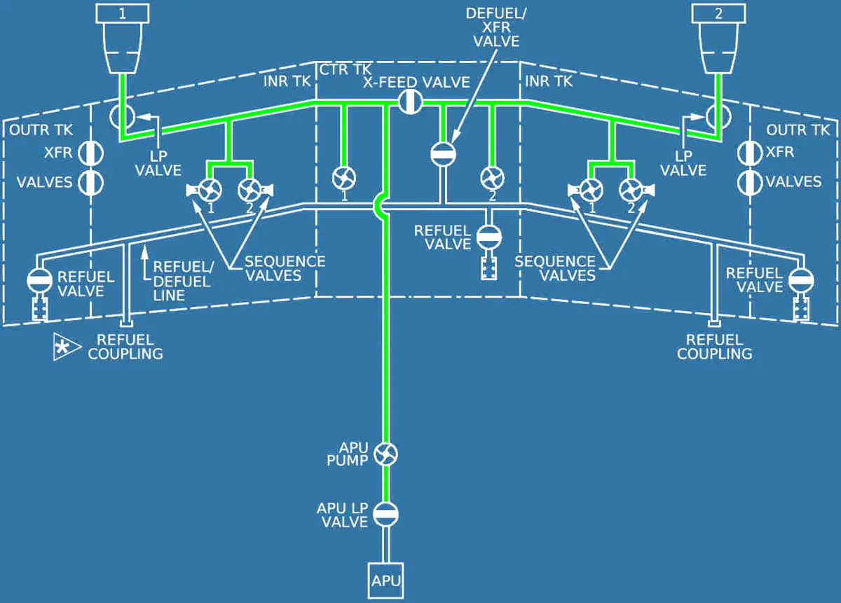
APU FEED
- LP valve – installed at rear wall of CTR TK > isolate the apu fuel feed.
- Fuel supply – normally from LH crossfeed line.
- APU fuel pump – normally off
- Start when low pressure in LH crossfeed line
- pressure switch in LH crossfeed line – controls APU pump operation.
- 21.7 psi – Re-start
- 23.3 psi – OFF
- When the A/C is on ground, it is possible to operate the APU fuel pump to purge the fuel line. The FUEL VENT P/BSW in APU compartment is used to operate the pump and to open the LP fuel valve.
- To prevent leaked fuel from spilling into the area of the fuselage (AFT Cargo Compartment, Bilge area, THS Compartment), the APU fuel supply line is shrouded. The shroud is connected to a Drain Mast which is located AFT of the MLG Doors.
REFUEL/DEFUEL
- flow of fuel into or out of the aircraft.
- Defuel/Transfer valve – interconnects the right hand engine supply line with the Refuel Gallery and allows fuel transfers and defueling operations.
- The main fuel pumps remove the fuel from the fuel tanks and supply it to refuel/defuel gallery till coupling where it can be removed from the aircraft.
- Refuel valve – Each refuel valve, one per tank, is the interface between the refuel gallery and the related fuel tank. It has a manual plunger for manual refueling.
- During a refuel operation, the outer cell is filled first. When it is full, fuel flows into the inner cell through the spill pipe which connects the two cells together.
- The diffusers, installed on refuel lines, diffuse fuel into the tanks with minimum turbulence and electrostatic build-up.
- Max pressure – 50 PSI (nominal pressure)
- Max suction – 11 PSI
- The air inlet valve lets air into the refuel gallery after refueling. Thus fuel can drain from the refuel gallery through the fuel drain valve.
- The fuel drain valves are closed by fuel pressure in the refuel gallery. When the pressure source is removed, the valve opens to allow fuel to drain from the refuel gallery into the wing tank.
- Overwing refueling points – when a pressure refuel source is not available — OPTIONAL. Not in our/new aircraft.
- Sometimes indicating light doesn’t come on the refuel panel – this is due to coldness – apply some heat by hand. Don’t tap.
- Why 3 time fuel sample –
- Hydrant systems have their own tank (filter) capacity of approx 600L. That’s why it is required to take a sample again once 600L is filled, normally we take after 1000L (middle). (Data needs to confirm).
- If refueling from a Tanker – 1 time is mandatory – initially.
- If full – high level light will come (high level sensor) – if tested this time – light will extinguish.
- On battery refueling – 40 sec self test then starts. On battery, refuel valves move slowly. So always check the fuel quantity at normal power.
- During fuel transfer – best practice is – to control the fuel (start/stop) – use the crossfeed valve. Usually, Crossfeed valve respond quickly, so we have better control. (Unauthorized procedures). Don’t tell.
- The correct procedure is first unload (off) the pumps then close the crossfeed valve.
- Fuel transfer in NEO
- Wing outer to inner tank
- Main fuel transfer system
- CTR to Left tank
- CTR to right tank
- Refueling is in ATA 12. – servicing. Usually doesn’t require systems to be operated.
- Defueling is in ATA 28. – because the system needs to operate.
- During fuel transfer/defuel – defuel/transfer till fault light. if we required to remove all fuel (zero), then put the mode selector to ON position and physically monitor to avoid dry running of pumps. Further we can use a drain tool to remove unusable fuel from the tank.
- If fuel spillage from surge tank – follow TSM procedures – 28-25-00-810-816-A and fill the form.
- During refueling – to avoid spillage – as per amm – crossfeed – off, mode selector – auto, CTR TK Pump 1 & 2 – off.
- Location of manual plunger – panel 511JB/611JB.
- Refuel/Defuel coupling
- 2.5 inch
- Breaking point
- During refueling – first outercell will fill then inner cell via spill pipe. When inner cell consumed fuel from outer cell to inner cell via transfer valve.
- Defuel/transfer valve – connect to refuel gallery.
- Center tank overflow/overfueling – to RH wing tank.
- Center tank venting – to LH surge tank.
- Refuel v/v – close command by FLSCU, when High level sensor immersed.
- Refueling – flap/slat zero.
- Refueling panel – 800vu
- FOB indication degraded (degraded display)- 2 Amber dash – accuracy not degraded beyond 5%.
- FQIC – calculate mass of fuel with accuracy of 1% (normal display).
- Low level sensor – dry for 5 min – CTR TK stop.
- Below 750 kg
- Intercel transfer valve – logic
- Full level sensor
- CTR TK Pump stop / restart logic.
- CTR TK Pump 500 kg logic
- Idg shut-off sensor
- 5000 and 250 kg logic for auto XFR fault.
- Pr. Switch in fuel pumps – 6 psi
- Sequence valve – 5 psi less (wing tank)
MODE SEL pb
- AUTO: Control of center tank pumps is automatic:
- They run at engine start for 2 min,
- Before or after the engine start sequence, the pumps run if the slats are retracted,
- They stop automatically 5 min after center tank low level is reached.
- MAN: Flight crew manually controls the center tank pumps with the center tank pumps’ pushbutton.
- FAULT light: Amber light comes on, and ECAM caution comes on when the center tank has more than 250 kg of fuel and the left or right wing tank has less than 5000 kg.
Fuel Level Sensing
- Controlled by Fuel Level Sensing Control Units (FLSCU).
- Fuel Level sensors – 5 type
- high level sensor
- low level sensors
- full level sensors
- underfull level sensors
- overflow level sensors
- temperature sensors
Fuel Quantity Indicating
- Quantity Indicating Computer (FQIC)
- Fuel probes
- Cadensicons
Manual Magnetic Indicators
- 4 Magnetic level indicators per wing and one per center tank.
- The value on the MLI nearest to the wing bottom skin is the relevant one.
- It is not necessary to have electrical power to use the MMIs.
- The MMI indications, the aircraft attitude value and the fuel relative density, are used with AMM tables to give the amount of fuel in each tank.
- MLI – Numbering – from 2 not 1 – (2,3,4,5 – total 4).
- MLI accuracy : +- 5%
- Refueling with MLI or Checking Fuel quantity using MLI – ADIRU must be aligned, to consider a/c attitude – pitch & roll.
CDCCL
Critical Design Configuration Control Limitations (CDCCL)
- Some procedures identify a fuel system item that is in a category known as a Critical Design Configuration Control Limitation (CDCCL). This category is applicable to items that are identified as the possible source of ignition of fuel in a fuel tank.
- You must keep CDCCL items in a serviceable condition. It is possible that damage, wear or changes to a CDCCL item can cause a fuel tank explosion.
- CDCCL items are identified by a WARNING in the procedures where they occur. When a procedure identifies a CDCCL item, it is a mandatory condition that you do the instruction correctly and accurately as the procedure tells you.
PRECAUTIONS
- Don’t pull FQIC CB / or any fuel system CB.
COMPUTERS
- FQIC
- FLSCU
See the location of A320 Computers.