A320 ECAM FUEL PAGE
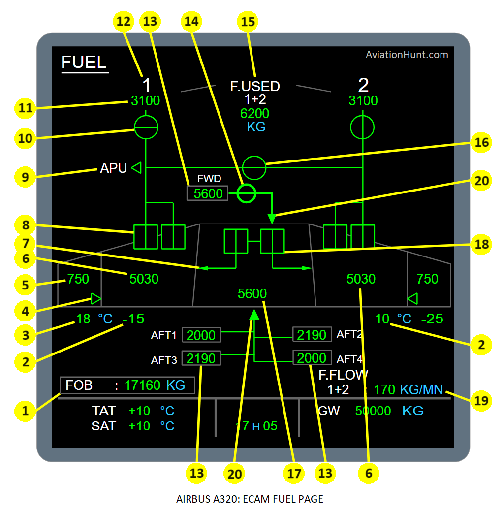
The A320 ECAM FUEL page with its parameters is described in the image above as follows:
- 1: Fuel On Board (FOB)
- 2: Inner tank fuel temperature LH (RH)
- 3: Outer tank fuel temperature LH (RH)
- 4: Transfer valve LH (RH)
- 5: Outer tank fuel quantity LH (RH)
- 6: Inner tank fuel quantity LH (RH)
- 7: Center to inner tank transfer
- 8: Left and Right tank pumps 1 and 2
- 9: APU fuel LP valve
- 10: Engine 1 (2) fire valve (or LP valve)
- 11: Fuel used – Engine 1 (2)
- 12: Engine number
- 13: ACT fuel quantity
- 14: Forward ACT isolation valve
- 15: Total fuel used
- 16: Fuel crossfeed valve
- 17: Center tank fuel quantity
- 18: Center tank pumps
- 19: Total fuel flow
- 20: Additional Center Tank (ACT) transfer
- Fuel links
Reference Aircraft: A320neo/LEAP-1A26
1. Fuel on board
- The units may either be in KG or LB, depending on the DMC pin program.
- The fuel on board quantity is displayed in 5 digits. LBS by step of 40 LBS or KG by step of 20 KG.
- Normal case, the digital value comes into view in green.
- In case of degraded data (indication from FQI), the two least significant digits are dashed with two amber lines across.
- The digital value is replaced by amber XX, when no valid data are available from the FQI bus.
- The digital value is comes into view an half amber box when:
- As soon as one of the two wing transfer valves is faulty, OR
- An ACT amber box is displayed, OR
- The center tank is installed and then a center tank pump is faulty with the engine 1 or 2 corespeed is at IDLE or above.
FUEL QUANTITY – ADVISORY
An advisory appears in flight phases 2 and 6, when the difference between the fuel quantities in the two wings is greater than 1500 kg (3300 lb). The wing inner and outer tank indications pulse with the highest fuel level.
2. Inner cell temperature LH (RH)
- Digital value from the FQI. The display can vary from -99 to +99 deg.C with 1 deg.C resolution.
- It is normally displayed in green.
- It becomes pulsing green when either the high or the low temperature advisory is reached.
- It turns amber when either the high or the low limit of the inner cell temperature is reached.
- An advisory only appears in phases 2 and 6, when the fuel temperature is above 45 °C or below -40 °C.
- The value displayed is replaced by amber XX, when no valid data are available.
3. Outer cell temperature LH (RH)
- Digital value from the FQI. The display can vary from -99 to +99 deg.C with 1 deg.C resolution.
- It is normally displayed in green.
- It becomes pulsing green when either the high or the low temperature advisory is reached.
- It turns amber when either the high or the low limit of the outer cell temperature is reached.
- An advisory only appears in phases 2 and 6, when the fuel temperature is above 55 °C or below -40 °C.
- The value displayed is replaced by amber XX, when no valid data are available.
- No data is displayed if the outer cell temperature probe is in a dry state.
4. Fuel transfer valve LH (RH)
- Valve closed: No triangle is displayed when the valve is normally closed.
- Valve open and green: when at least one valve is normally fully open.
- Valve amber in a transitional status: when rear transfer valve is neither fully open nor fully closed at a time, OR when the forward transfer valve is neither fully closed nor fully open at a time AND the DC2 bus is ON.
- Valve open and amber: when both valves are fully open and any transfer valve fails to shut,
- Valve replaced by amber XX: when the valve status is not known, or one received valve status is inconsistent (valve fully closed with valve fully open at a time).
5. Outer cell fuel quantity LH (RH)
- The units may either be in KG or LB, depending on the DMC pin program.
- Digital value from the FQI are displayed on 3 digits for KG (by step of 10KG) and 4 digits for LBS (by step of 20 LBS).
- It is normally displayed in green.
- In case of degraded data (indication from FQI), the two least significant digits are dashed with two amber lines across.
- The value displayed is replaced by amber XX, when the information is not available from the FQI bus.
- The digital value is displayed in an amber box when the onside wing transfer valve is faulty.
6. Inner cell fuel quantity LH (RH)
- The units may either be in KG or LB, depending on the DMC pin program.
- Digital values from the FQI are displayed on 4 digits for KG (BY step of 10KG) and 5 digits for LBS (by step of 20 LBS).
- It is normally displayed in green.
- In case of degraded data (indication from FQI), the two least significant digits are dashed with two amber lines across.
- The digital value is replaced by amber XX, when the information is not available from the FQI bus.
- It is displayed in amber when: DC battery/DC essential shedding contactor is closed and There is a confirmed wing tank overflow (five second confirmation time) or a confirmed wing tank overflow cleared in the last five seconds.
7. Center to inner transfer indication
- Nothing is displayed when:
- Data from SDAC are invalid
- The valve is fully closed
- The valve is fully closed and fully open at the same time (transitory state).
- Full triangle and ducts are displayed in amber when:
- the pump pushbutton is OFF
- The pump auto shut off is required and there is not the mode select pushbutton on MANUAL.
- In all other cases, triangle and ducts are displayed in green.
8. Left and Right tank pumps 1 and 2
- The pump symbol is normally displayed in green.
- It turns amber when the pump is not supplied (when the pump contactor is OFF).
- In case of low pressure, LO is displayed in amber.
- It is replaced by amber XX when no valid data are available.
9. APU fuel LP valve
- The APU title is white and the triangle and link are normally green.
- The APU title and the triangle are white when the APU fuel LP valve is fully closed.
- The APU title alone is displayed in amber: When the APU master switch is set to ON or the APU fire push button set to OUT. and, The APU fuel LP valve is fully closed.
- The APU title and triangle (plain) is amber if jammed open: the APU fire pushbutton is OUT, or the APU master switch is not ON for longer than 1mn
- The APU title and the triangle (outline only) are amber when the APU fuel LP valve is neither fully closed nor fully open at a time.
- It is replaced by white APU title and amber XX when the two states fully open and fully closed are simultaneously detected or no valid data is available from the SDAC.
10. Engine 1 (2) fire valve
- The engine fire valve is green when normally open.
- It is amber when fully open with the related ENG FIRE pushbutton OUT and/or ENG MASTER lever set to OFF.
- Valve fully closed displayed in amber.
- It is amber when the valve is neither fully closed nor fully open.
- It is replaced by amber XX when the fully open and fully closed states are simultaneously detected. (or no data from the SDAC is available)
11. Fuel used – Engine 1 (2)
- This digital value, resulting from fuel flow integration inside DMC, can vary from 0 to 45360 KG, with 10 KG resolution.
- It is normally displayed in green.
- In case of degraded data (if indication of fuel flow is not valid in flight after 60s) , all the digits are dashed, together with the TOTAL indication (FUEL USED 1+2) with two horizontal amber lines (fuel flow value from the FADEC bus not correctly received by the DMC in flight).
- It is replaced by amber XX after a long DMC power supply interruption in flight. In this case, the fuel used computation stops until the next starting sequence on ground.
- As a result, the total fuel used is also replaced by two amber XX.
12. Engine Number
The number of each engine is normally white. It is amber when the engine is stopped (core speed not at idle or not above idle).
13. ACT Fuel Quantity
- It is normally shown in green in a gray box.
- The digital value is pulses green when:
- There is no incorrect fuel data, and
- The ACT transfer-pump pushbutton-switch is pushed (ON legend on), and
- The ACT transfer is not shown green in manual mode, and
- The highest priority ACT transfer in amber condition is correct, and
- The ACT box is not amber.
- When the ACT fuel quantity is degraded and when ACT fuel quantity is valid, the two least significant digits are shown dashed with amber lines.
- Amber XX replaces the digital value, when no correct data are available.
- The box around the digital value becomes amber when:
- There is no incorrect in the fuel data, and
- The center-tank fuel quantity is an amber box, or
- The ACT tank is defective, or
- The ACT transfer is defective.
14. Forward ACT isolation-valve
- Valve closed and green when:
- The forward ACT isolation-valve is closed, and
- The forward ACT inlet-valve is open and its position agrees with the selected position: Open.
- The valve is closed and amber when:
- The forward ACT isolation-valve is unusually closed (the valve is closed and this position disagrees with the selected position: Open), and
- The forward ACT inlet-valve is open and its position agrees with the selected position: Open.
- The valve is open and green when:
- The forward ACT isolation-valve is open, and
- The forward ACT inlet-valve is open and its position agrees with the selected position: Open.
- The valve is open and amber when:
- The forward ACT is not installed and: The forward ACT isolation valve is unusually open (the valve is open and this position disagrees with the selected position: Closed), or
- The forward ACT is installed and: The forward ACT isolation-valve is unusually open (the valve is open and this position disagrees with the selected position: Closed), or The forward ACT inlet-valve is unusually open (the valve is open and this position disagrees with the selected position: Closed).
- Amber XX replaces the valve status when:
- The forward ACT is not installed and: The forward isolation-valve is open and the data are not correct, or The forward ACT isolation-valve is closed and the data are not correct, or
- The forward ACT is installed and: The forward isolation-valve is open and the data are not correct, or The ACT4 inlet valve is open and the data are not correct, or The ACT4 is selected for the transfer and the data are not correct, or The forward ACT isolation-valve is open and the data are not correct, or The ACT transfer-pump pushbutton-switch is pushed (ON legend on) and data are not correct.
15. Total Fuel Used
- A total fuel used is computed and normally displayed in green.
- As soon as one (at least) of the two fuel used values is dashed (degraded data), then the total fuel used is also dashed.
- As soon as one (at least) of the two fuel used values is replaced by amber XX, then the total fuel used is also replaced by amber XX.
- The Total Fuel Used remains displayed after the ECU power cut.
16. Crossfeed valve
- The crossfeed valve is green when normally open.
- It is green when normally closed.
- It is amber if jammed closed.
- It is amber if jammed open.
- It is amber when in transit.
- It is replaced by amber XX when the fully open and fully closed states are simultaneously detected, or no valid data is available from the SDAC
17. Center-tank fuel quantity
- It is normally displayed in green.
- The units may either be in KG or LB, depending on the DMC pin program.
- Two dashes appear across the last two digits when the FQI is inaccurate.
- The center tank indication is boxed amber, if both center tank transfer valves fail in the closed position.
18. Center tank pumps 1 and 2
- The tank pump symbol is normally displayed in green with a vertical bar.
- It turns amber with a horizontal bar when the center transfer control valve is fully closed.
- It is displayed in amber with vertical bar when either:
- the related transfer control switch is set to OFF or
- auto shut off is required and manual mode not selected.
- It is replaced by amber XX when data from SDAC are not valid or when the transfer control valve is detected in one of the following positions:
- neither closed nor open (confirmed 6s)
- fully open and fully closed simultaneously (transmission failure case).
- It is displayed in green with horizontal bar when:
- the center transfer control valve is fully closed
- the related center tank pump auto shut off is required
- the related transfer control switch is set to off
- the related wing center tank pump is not in low level or the aircraft is on ground
- manual mode not selected.
19. Total Fuel Flow indication
- The total fuel flow value is displayed in green. It is replaced by amber XX when no valid data is available.
- The value can vary from 0 to 999 KG/MN by 1KG/MN step.
Fuel links
- Link to Engine 1 (2): This link is not displayed when the fire valve is replaced by amber XX. It is displayed in green when the valve is green and displayed in amber when the valve is amber.
- Link from left/right pump: This link is not displayed when the pump is OFF. It is displayed in green when the pump is green and displayed in amber when the pump is amber.
- Link from left/right auxiliary pump: This link is not displayed when the pump is OFF. It is displayed in green when the pump is green and displayed in amber when the pump is amber.
- Link to APU: This link is not displayed when the fire valve is replaced by amber XX. It is displayed in green when the valve is green and displayed in amber when the valve is amber.
- Link between the APU and the Crossfeed valve: This link is displayed in green.
- Link between the crossfeed valve and Engine 2: This link is displayed in green.