The A320 ATA 27 Technical Notes provide brief and to-the-point information about the Airbus A320 Flight Control System, including its components and their functions. ATA Chapter 27 deals with the flight controls of an aircraft. It includes all control surfaces that are used to manage the attitude and direction of the aircraft during flight.
A320 FLIGHT CONTROL SYSTEM
Airbus A320 Flight Control System is based on fly-by-wire technology which was designed and certified to render the new generation of aircraft even more safe, cost-effective, and pleasant to fly. Technically this system of A320 is called the Electrical Flight Control System (EFCS).
- All flight control surfaces are made of composite materials except for the slats which are made of aluminum alloy.
- All flight control surfaces are electrically controlled and hydraulically operated.
- As a backup, the stabilizer and rudder are mechanically controlled and hydraulically operated.
- Pilots use side sticks to fly the aircraft in pitch and roll.
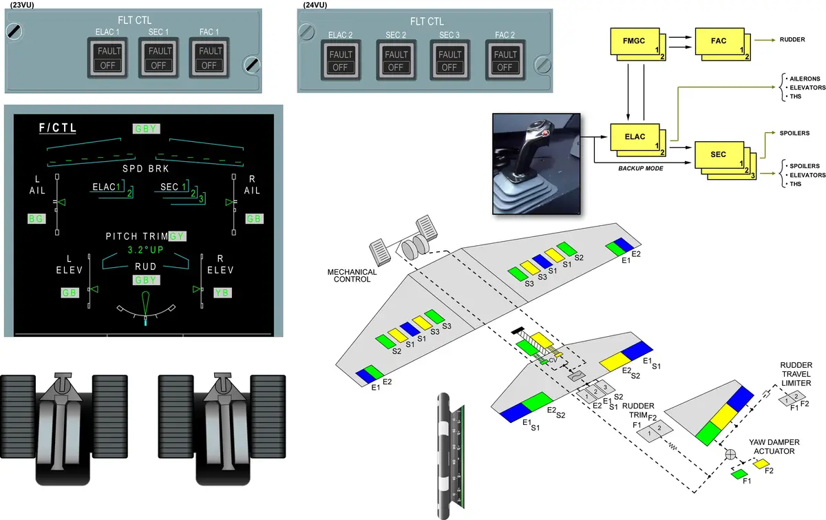
COMPUTERS
Electrical Flight Control System (EFCS) computers –
- 2 Elevator Aileron Computers (ELAC) for pitch and roll control,
- Normal elevator and stabilizer control.
- Aileron control.
- 3 Spoiler Elevator Computers (SEC) for pitch and roll control,
- Spoilers control.
- Standby elevator and stabilizer control.
- 2 Flight Augmentation Computers (FAC) for yaw control,
- Electrical rudder control.
- 2 Flight Control Data Concentrators (FCDC) for indication and maintenance tests,
- Flight Control Data Concentrators (FCDC) acquire data from the ELACs and SECs and send it to the electronic instrument system (EIS) and the centralized fault display system (CFDS).
- 2 Flight Management Guidance Computer (FMGC) for autopilot commands,
- 2 Slat Flap Control Computers (SFCC) for slat and flap control.
See the location of A320 Computers.
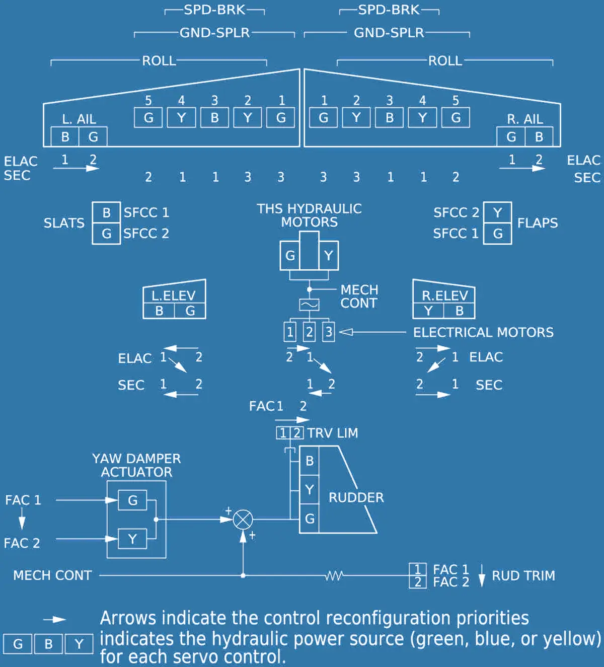
ACTUATORS
- The Aileron surface is powered by two servo controls.
- Each Spoiler surface is powered by a single servo control.
- The Flaps and Slats surfaces are powered by their dedicated PCU.
- The Rudder surface is powered by 3 servo controls.
- The THS is moved by one actuator.
- The Elevator surface is powered by two servo controls.
FLIGHT CONTROL SURFACES
PITCH
- Pitch control is achieved by – 2 Elevators and THS
- Elevators are used for short-term activity.
- THS is used for long-term activity.
ROLL
- Roll control is achieved by 1 Aileron and
- Spoilers 2 to 5 on each wing. — (Roll Spoilers)
- Numbered from wing root to wing tip.
YAW
- Yaw control is fulfilled by the rudder.
- Rudder is used during crosswind take-off and landing, and in case of engine failure (thrust asymmetry).
- Yaw damper function controls the rudder for Dutch roll damping and turn coordination.
Learn the Basics: How an Aircraft Turns in the Air?
SPEED BRAKES
- The speed brake function is used in flight to increase the aircraft drag.
- Spoilers 2, 3, 4 are used.
- Roll orders and speed brake orders are added with priority given to the roll function.
GROUND SPOILERS
- Ground spoiler function is used to destroy the lift during landing and in case of aborted take-off.
- All spoilers are used.
HIGH LIFT
- High lift function is achieved by slats and flaps.
- 2 flaps, inboard and outboard,
- 5 slats on each wing,
- numbered from wing root to wing tip.
- The A321 is equipped with double slotted flaps.
AILERON DROOP
- The aileron droop function increases the lift on the part of the wing which has no flaps.
- Ailerons are deflected downwards when the flaps are extended.
CONTROLS
SIDE STICK
- Two side sticks are used for manual pitch and roll control.
- spring loaded to neutral position.
- Each side stick has a push button used for autopilot disconnection and to take priority over the other side stick.
SPEED BRAKE LEVER
- Speed brake lever controls the position of the speed brake surfaces and pre-selection of the ground spoiler function.
- For the speed brake function, the lever has to be pushed down and placed in the required position.
- To arm the ground spoilers for automatic extension, the lever must be pulled UP when in the retracted position.
- Speedbrake extension is inhibited, if one of the following occurs:
- SEC1 and SEC3 both are faulty, or
- An elevator (L or R) is faulty, or
- Angle-of-attack protection is active, or
- Flaps are in configuration FULL, or
- Thrust levers are above MCT position, or
- Alpha Floor is activated.
THS CONTROL
- THS is automatically trimmed during flight.
- After touchdown, the THS is automatically trimmed to neutral position.
- THS mechanical control is used to set the pitch trim before take-off or when the automatic pitch trim is not available.
- Trim position is indicated in degrees on a scale adjacent to each trim wheel.
- Mechanical control of the THS is available from the pitch trim wheel at any time, if either the green or yellow hydraulic system is functioning.
- Mechanical control from the pitch trim wheel has priority over electrical control.
RUDDER PEDALS
- Two sets of pedals enable the rudder mechanical control.
- The pedals can be individually adjusted.
RUDDER TRIM
- The rudder trim control switch operates the electrical trim actuator to move the rudder to a new neutral position.
- The rudder trim RESET switch resets the trim position to zero.
- The rudder trim indicator displays rudder trim position in degrees.
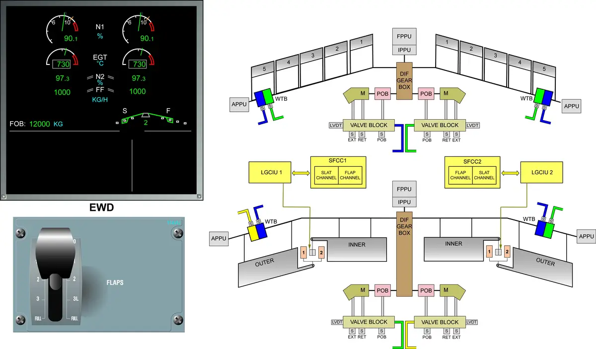
FLAP CONTROL LEVER
- The flap control lever selects simultaneous operation of slat and flap.
- It has five positions.
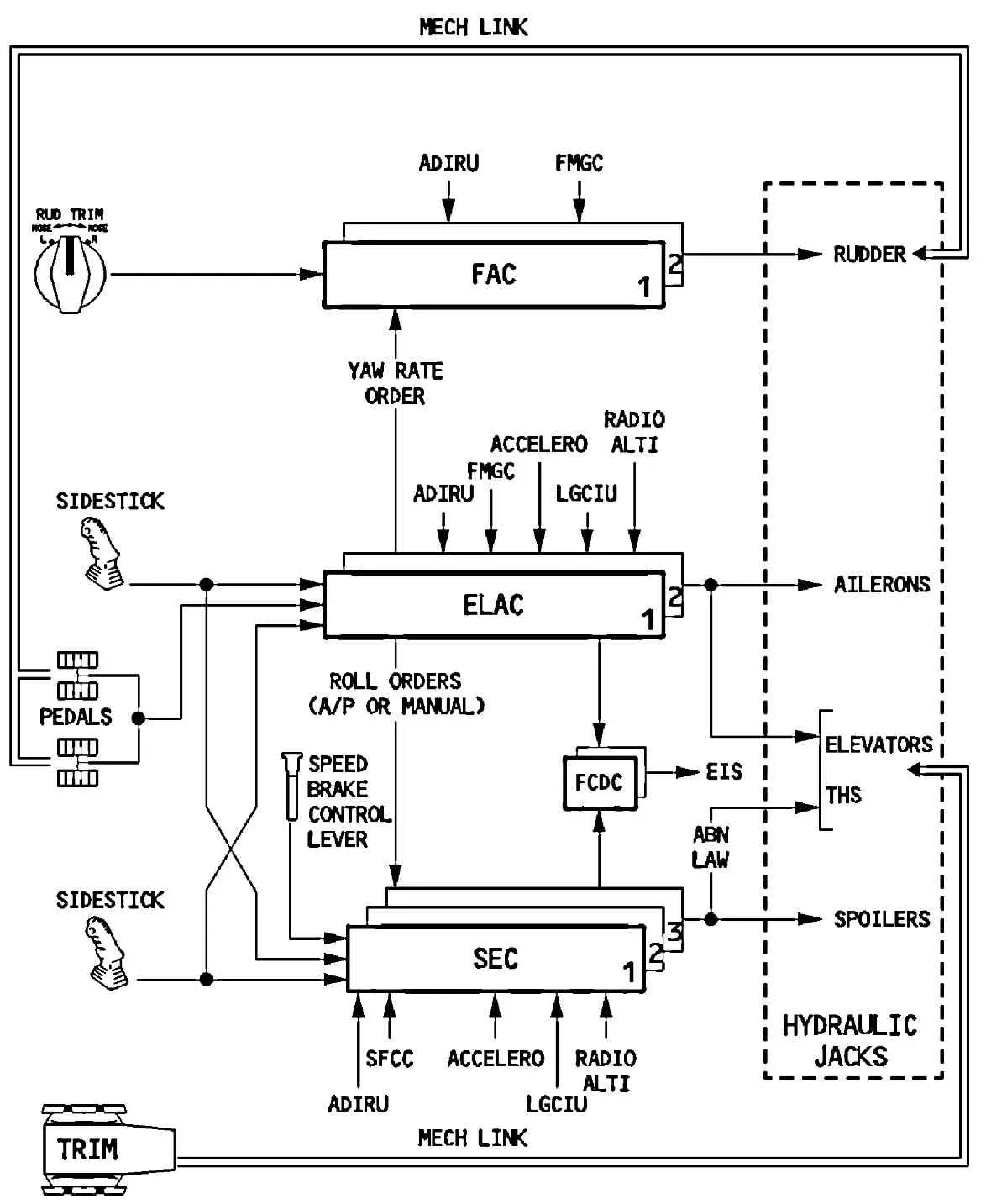
FLY BY WIRE PRINCIPLE
- The pilots use the side sticks to fly the aircraft in pitch and roll (and in yaw indirectly through turn coordination).
- The pilot’s side stick orders are sent to the flight control computers.
- These computers convert the orders into an aircraft objective.
- The computers send surface deflection orders to the surfaces in order to achieve the aircraft objective. Then, the computers monitor the position feedback of the surfaces. This loop is called “inner loop”.
- The computers also receive an aircraft response and compare it to the demand (coming from the orders), this loop is called an “outer loop”. The fly by wire design requires the aircraft to be servo-looped.
- However, regardless of the pilot’s inputs, the computer prevents:
- excessive maneuvers,
- flight outside the safe flight envelope.
- Autopilot commands are given directly to the computers.
SURFACES
- All the flight control surfaces are hydraulically operated by actuators which receive electrical signals from the computers. — Electrically controlled and Hydraulically operated.
- The rudder and the Trimmable Horizontal Stabilizer (THS) can also be mechanically controlled.
- All the actuators are hydraulically powered by one of the three hydraulic circuits, except the rudder trim actuator, the rudder travel limitation actuator and the THS servo-motors which are electrically driven.
- There are two servo controls for each aileron, for each elevator and for the yaw damping function. In normal configuration, one servo control actuates the surface. It is called active servo control. The second, which follows the surface deflection, is in damping mode. When only the mechanical control of the pitch trim is available (all computers inop), the centering mode is applied to the elevators. The actuators are hydraulically maintained in neutral position.
ACTUATION
ELEVATORS
- Two electrically-controlled hydraulic servo jacks drive each elevator.
- Each servojack has three control modes
- Active: The jack position is electrically-controlled.
- Damping: The jack follows surface movement.
- Centering: The jack is hydraulically retained in the neutral position.
STABILIZER
- A screwjack driven by two hydraulic motors drives the stabilizer.
- The two hydraulic motors are controlled by :
- One of three electric motors, or
- The mechanical trim wheel.
AILERONS
- Each aileron has two electrically controlled hydraulic servo jacks.
- One of these servojacks per aileron operates at a time.
- Each servojack has two control modes :
- Active : Jack position is controlled electrically
- Damping : Jack follows surface movement.
- The system automatically selects damping mode, if both ELACs fail or in the event of blue and green hydraulic low pressure.
SPOILERS
- A servojack positions each spoiler.
- Each servojack receives hydraulic power from either the green, yellow, or blue hydraulic system, controlled by the SEC1, 2 or 3.
- The system automatically retracts the spoilers to their zero position, if it detects a fault or loses electrical control.
RUDDER
- Three independent hydraulic servo jacks, operating in parallel, actuate the rudder. In automatic operation (yaw damping, turn coordination) a green servo actuator drives all three servojacks. A yellow servo actuator remains synchronized and takes over if there is a failure.
RUDDER TRIM
- The two electric motors that position the artificial feel unit also trim the rudder. In normal
- operation, motor N° 1 (controlled by FAC1), powers the trim, and FAC2 with motor N° 2 remains synchronized as a backup.
- In manual flight, the pilot can apply rudder trim via the rotary RUD TRIM switch on the pedestal.
- The pilot can use a button on the RUD TRIM panel to reset the rudder trim to zero.
- With the autopilot engaged, the FMGC computes the rudder trim orders. The rudder trim rotary switch and the rudder trim reset pushbutton are not active.
FLIGHT CONTROL LAWS
- The Electrical Flight Control System (EFCS) computers convert pilot inputs into aircraft control objectives.
- The computers calculate the control laws that are used to compute the surface deflections. The system has a high degree of redundancy and it will reconfigure itself when failures occur.
NORMAL LAW
- In normal condition, the normal law is used to compute the surface deflection orders.
- Normal laws provide full flight phase envelope protection. This means that the aircraft will be protected from excessive maneuvers during all flight phases.
ALTERNATE LAW
- The alternate law is automatically introduced as soon as the normal law is lost due to system failures.
- The alternate law gives reduced protection.
DIRECT LAW
- The direct law is automatically introduced when further failures occur.
- In direct law all protections are lost. There is a direct relationship between the side stick orders and the surface.
- The direct law is automatically activated on ground.
MECHANICAL BACK-UP
- The mechanical back-up lets the aircraft be controlled during a temporary complete loss of electrical power or flight controls computers.
- Longitudinal control is achieved using the trim wheels to control the THS, as the elevators are kept at zero deflection.
- Lateral control is achieved from the rudder pedals.
- Hydraulic power is still needed to operate the surfaces of the THS and the Rudder.
SLAT AND FLAP SYSTEM
- Two SFCCs, each containing one slat channel and one flap channel.
- Each system is driven by a Power Control Unit (PCU).
- A PCU which is made of two independent hydraulic motors coupled by a differential gearbox.
- Then torque shafts and gearboxes transmit the mechanical power to the actuators which drive the surfaces.
- The motors use green and blue hydraulic power for the slats, and yellow and green power for the flaps.
- Each motor has its own valve block and Pressure Off Brake (POB).
- The POB locks the transmission when the slat or flap surfaces have reached the selected position or if hydraulic power fails.
- Wing Tip Brakes (WTBs) are provided in order to stop and lock the system when major failures are detected. They are hydraulically activated and can only be reset on ground.
- The WTBs which activate in the case of an uncommanded movement of the surfaces, such as runaway, asymmetry or over speed. They cannot be released in flight. They use blue and green hydraulic power for the slats and for the right wing flaps, and blue and yellow hydraulic power for the left wing flaps.
- Position Pick-Off Units (PPUs) send slat and flap position feedback to the SFCCs and ECAM.
- Flap sensors installed between inboard and outboard flaps inhibit further flap operation when a flap attachment failure is detected.
- The signal is sent to the SFCCs via the Landing Gear Control and Interface Units (LGCIU)
- To prevent an aircraft stall, slats cannot be fully retracted at high angles of attack or low speeds (Alpha/speed lock function).
- The FLAPS lever has five positions: 0, 1, 2, 3, and FULL.
- Two configurations correspond to position 1: Configuration 1 and Configuration 1 + F.
- When in Configuration 1 + F, the flaps retract to 0 ° automatically at 210 kt (before the airspeed reaches VFE).
- When in configuration 1, the flaps extend to 10 ° automatically at 100 kt.