A320 ECAM FLT CTL PAGE
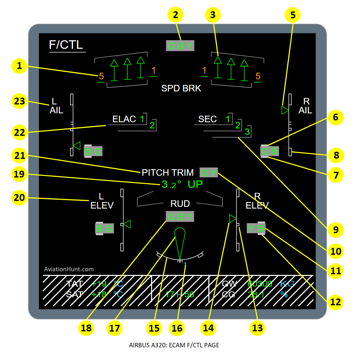
The A320 ECAM F/CTL page with its parameters is described in the image above as follows:
- 1: Spoilers status (left)
- 2: Hydraulic system pressure indication
- 3: Spoilers status (right)
- 4: FCDC Message
- 5: Aileron position
- 6: Servo control hydraulic pressure
- 7: Servo control electrical status
- 8: Aileron scale
- 9: SEC computer operation
- 10: Horizontal stabilizer hydraulic pressure
- 11: Elevator (right) hydraulic pressure
- 12: Elevator (right) electrical status
- 13: Elevator (right) scale
- 14: Elevator (right) position
- 15: Rudder scale
- 16: Rudder trim position
- 17: Rudder position
- 18: Rudder hydraulic status
- 19: Trimmable horizontal stabilizer position
- 20: Elevator (left)
- 21: Trimmable horizontal stabilizer control
- 22: ELAC operation
- 23: Aileron indication (left)
Reference Aircraft: A320neo/LEAP-1A26
1. Spoilers status indication
- The spoiler is represented out and green, when the spoiler status is transmitted correctly from the FCDC bus, the spoiler is extended and available, also from the FCDC bus.
- The spoiler is represented in and green, when the spoiler status is transmitted correctly from the FCDC bus, the spoiler is retracted and available, also from the FCDC bus.
- The spoiler is represented out and amber when the spoiler status is transmitted correctly from the FCDC bus, the spoiler is extended and faulty (hydraulic failure or spoiler servo-loop failure, but transducer position valid), as transmitted from the FCDC bus.
- The spoiler is represented in and amber when the spoiler status is transmitted correctly from the FCDC bus, the spoiler is retracted and faulty (hydraulic failure or spoiler servo-loop failure, but transducer position valid), as transmitted from the FCDC bus.
- The spoiler is replaced by amber X when the spoiler position is transmitted as not valid (transducer position not available) from the FCDC bus, or the spoiler status information (SECs fault or off) is not available.
2. Hydraulic system pressure indication
- The hydraulic system pressure indications (G, B, Y) are displayed on a gray background.
- The letter which represents the hydraulic system is normally displayed in green.
- It is displayed in amber when the related pressure is lower than 1450 PSI or when the FWC has transmitted a low press to the DMC.
- The letter is not displayed when the information is not transmitted correctly to the DMC.
3. Spoilers status (right)
- Refer to the left spoilers (point#1) as the same principles apply.
4. FCDC Message
5. Aileron position
- A pointer (triangular) moving along a fixed scale represents the aileron position. It is normally displayed in green.
- It is displayed in amber when there is a low pressure of the relevant hydraulic systems, or when an aileron fault is transmitted from both hydraulic systems concerned.
- The pointer is replaced by amber XX positioned in front of the 0°aileron scale when the information of the actuator position is not valid from FCDC (ELACs fault or off or both servo-control failure).
6. Servo control hydraulic pressure
- Two normally green letters represent the hydraulic systems involved (e.g. GREEN and BLUE), they are displayed in amber when the relevant pressure is lower than 1450 PSI, as transmitted by the SDAC.
- They are not displayed when the pressure value is not transmitted correctly by the SDAC.
7. Servo control electrical status
- Around the servo control hydraulic status, the electrical status is displayed in amber when the corresponding servo control is not electrically available as transmitted by the FCDC. It is not displayed otherwise.
8. Aileron scale
- The scale for the aileron is always displayed in white.
9. SEC computer operation
- SEC is always white; the computer number 1, 2 or 3 is normally displayed in green. The half frame below is normally displayed in gray.
- The number and the half frame are displayed in amber when the computer is transmitted as faulty (or OFF) by the FCDC bus.
- The number is replaced by an amber X, the half frame remaining gray when the information is not available from the FCDC bus.
10. Horizontal stabilizer hydraulic pressure
- The horizontal stabilizer hydraulic pressure indications are displayed on a gray background.
- The letter for the hydraulic status is normally displayed in green.
- It is displayed in amber when the related hydraulic pressure is lower than 1450 PSI as transmitted by the SDAC.
- It is not displayed when the pressure value is not available from the SDAC.
11. Elevator (right) hydraulic pressure
- Two normally green letters represent the hydraulic systems involved (e.g. GREEN and BLUE), they are displayed in amber when the relevant pressure is lower than 1450 PSI, as transmitted by the SDAC.
- They are not displayed when the pressure value is not transmitted correctly by the SDAC.
12. Elevator (right) electrical status
- Under the servo control hydraulic status, the electrical status is displayed in amber when the corresponding servo control is not electrically available as transmitted by the FCDC. It is not displayed otherwise.
13. Elevator (right) scale
- The scale is displayed in white.
14. Elevator (right) position
- A pointer moving along a fixed scale represents the elevator position. It is normally displayed in green.
- It is displayed in amber when there is a low pressure of both hydraulic systems, or when an aileron fault is transmitted from both hydraulic systems concerned.
15. Rudder scale
- Displayed in white.
16. Rudder trim position
- The index is normally displayed in cyan and moves along the scale according to the present trim position. It is displayed in amber when both control systems are faulty as transmitted by the FWC. It is replaced by amber XX when the value for the trim position is not transmitted.
- The rudder trim position range is as follows:
- Between -25° and +25° for A320 and A321 CEO aircraft.
- Between -30° and +30° for all A318, all A319, A320 and A321 NEO aircraft.
17. Rudder position
- The rudder symbol is normally displayed in green. It is displayed in amber when the three hydraulic pressures drop below 1450 PSI as transmitted by the SDAC, or when the FWC transmits three LO PRESS for the three hydraulic pressures.
- It is replaced by amber XX when the value for the rudder position is not valid from SDAC (both SDAC fault or off or positioning sensor failure).
- The rudder position range is as follows:
- Between -27° and +27° for A320 and A321 CEO aircraft.
- Between -32° and +32° for all A318, all A319, A320 and A321 NEO aircraft.
18. Rudder hydraulic status
- Each one of the three letters G B Y is normally displayed in green.
- They are displayed in amber when there is a low press on the relevant hydraulic system.
- They are not displayed when the status for the relevant hydraulic system is not transmitted by the SDAC or by the FWC.
- The rudder hydraulic pressure indications are displayed on a gray background.
19. Trimmable horizontal stabilizer position
- The angle: The angle ranges from -13.5° to +4° and the UP direction (only displayed below -0.05°) are normally displayed in green.
- The angle and the DN (DOWN) direction (only displayed above +0.05°) are normally displayed in green.
- The angle and UP are displayed in amber when there is a low pressure on both the yellow system and the green system as transmitted by the SDAC or the FWC.
- The angle and DN are displayed in amber when there is a low pressure on both the yellow system and the green system as transmitted by the SDAC or the FWC.
- The value and the direction for the stabilizer position are not displayed and replaced by amber XX when the angle is not available.
20. Elevator (left)
- Refer to the right elevator as the same description applies.
- Points: 11, 12, 13, 14
21. Trimmable horizontal stabilizer control
- PITCH TRIM is normally displayed in white. It is displayed in amber when there is a THS jam as transmitted by the FCDC.
22. ELAC operation
- The letter 1 or 2 is normally displayed in green with the outline part in gray.
- They are displayed in amber when the relevant computer is faulty as transmitted by the FCDC.
- The figure is replaced by an amber X with the outline part gray when the computer status is not transmitted by the FCDC.
23. Aileron indication (left)
- Refer to the right aileron indication as the same description applies.
- Points: 5, 6, 7, 8