A320 ATA 36 Technical Notes provide brief and to-the-point information about the Airbus A320 Pneumatic System, including its components and their functions. ATA Chapter 36 titled Pneumatic covers systems that deliver large volumes of compressed air from various sources to user systems.
Reference aircraft – A320ceo/CFM56
A320 PNEUMATIC SYSTEM
The Airbus A320 pneumatic system receives compressed air from pneumatic air sources and supplies compressed air to user systems through ducts. The ducts are installed in the fuselage, belly fairing, and wings.
The control of the pneumatic system is usually automatic. Bleed-Air Monitoring Computers (BMCs) control the automatic function. The BMCs are installed in the avionics compartment. There is one BMC for each engine. You can also control the system manually. The pushbutton and selector switches on the overhead panel 30VU in the cockpit, control the manual function.
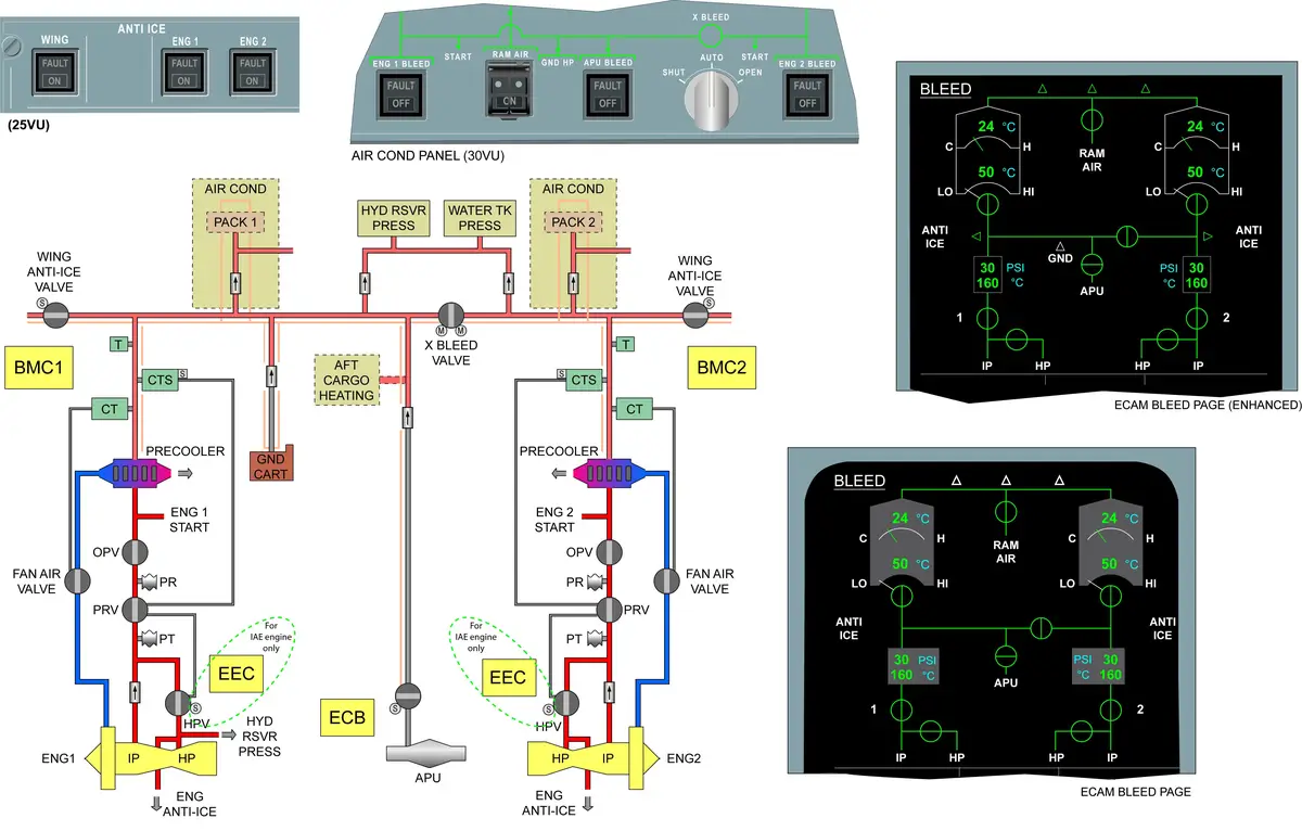
You can monitor the operation of the pneumatic system on the ECAM BLEED SD PAGE. The pushbutton switches on the overhead panel 30VU have no indication when the system operates correctly.
SOURCES
- CFMI engines – Air is bled from the 5th (IP) or 9th stage (HP).
- APU – The air is bled from the APU load compressor.
- The APU can supply bleed air up to an altitude of 20000 ft.
- HP ground connection.
USERS
- Wing ice protection system
- Air conditioning system
- Engine starting system
- Hydraulic reservoir pressurization system
- Pressurized water system
- Nacelle anti-ice valve (servo pressure)
SYSTEM
The distribution system supplies bleed air to user systems from various bleed air sources. It includes the following subsystems:
- Engine bleed-air supply-system
- APU bleed-air supply and crossfeed system
- Ground compressed-air supply-system
- Environment protection
COMPUTERS
- 2 BMCs monitor and control the pneumatic system operation.
- See the location of A320 Computers.
ENGINE BLEED AIR SUPPLY SYSTEM
- Bleed Air – IP stage – 5th sage >> at high engine speeds ; normal engine air-bleed configuration.
- Bleed Air – HP stage – 9th stage >> at low engine speeds ; when the pressure from the IP stage is insufficient.
- Air is normally bled from the intermediate pressure (IP) stage to minimize fuel penalty.
- When the HP bleed valve is closed, air is directly bled from the IP stage through an IP bleed check valve (fitted with two flappers).
- When the HP bleed valve is open, the HP stage pressure is admitted into the pneumatic ducting and closes the IP bleed check valve. Air is then bled from the HP stage only.
- HP bleed valve operation is fully pneumatic, Normally spring loaded to closed position.
- HPV – cannot be controlled from the cockpit.
- HPV open/close position displays on ECAM.
- HPV is a butterfly type valve which operates as a shut-off and pressure regulating valve.
- HPV is connected by a sense line to a bleed pressure regulator valve (PRV).
- PRV is installed in the duct downstream of the IP bleed check valve and the HPV.
- PRV is a butterfly type valve which operates as a shut-off and pressure regulating valve.
- PRV bleed valve operation is fully pneumatic, Normally spring loaded to closed position.
- PRV – Can be controlled in a closed position from the cockpit. — ENG 1(2) BLEED p/b.
- PRV open/close position displays on ECAM.
- As the PRV is connected to the HPV by a sense line, when the bleed is controlled OFF, both PRV and HPV are vented and closed simultaneously.
- PRV opening and closing can be controlled by a bleed PRV control solenoid. The solenoid is installed in the duct downstream of the bleed air precooler exchanger.
- The solenoid controls the bleed PRV which controls the HP bleed valve at the same time.
- Downstream of the PRV an overpressure valve (OPV) is installed to protect the pneumatic system against damage if overpressure occurs. It will close when downstream PRV pressure reaches the OPV closing value.
- Pressure regulated air is then routed to the users through the bleed air precooler exchanger (air-to-air) where it is cooled. Cooling is achieved by modulation of cold airflow from the engine fan, through a fan air valve controlled by a fan air valve control thermostat.
- The FAV operates pneumatically and is connected by a sense line to a fan air valve control thermostat. The thermostat is installed downstream of the precooler exchanger.
- Pressure transducer – downstream of PRV – ECAM indication
- Temperature sensor – downstream of precooler – ECAM indication
APU BLEED AIR SUPPLY AND CROSSFEED SYSTEM
- Bleed Air – Load compressor of the APU
- controlled by the APU bleed-control valve.
- When the APU bleed-control valve is in the open position, the Pressure Regulating Valves (PRV) of the engines close and shut-off the engine bleed-air supply. Thus, the distribution system supplies the APU bleed air to the user systems.
- The APU also has a surge control valve.
- ECB monitors the bleed air supply and also controls the APU bleed-load valve and the surge control valve.
- a crossbleed valve which isolates or connects the right and left bleed air and distribution systems.
- The APU bleed-air duct connects the APU to the crossbleed duct. A check valve is installed in the APU bleed-air duct which gives protection to the APU when a different source supplies bleed air with a higher pressure.
- The crossbleed duct has a crossbleed valve which controls the bleed air supply to the left and right bleed-air systems.
- When the engine PRV closes and the APU supplies the bleed air, then the crossbleed valve opens automatically.
- The crossbleed valve is an electrical shut-off valve (butterfly-type) controlled by the Bleed Monitoring Computer (BMC) for automatic operation. You can also operate it manually from the cockpit. Crossbleed valve has two motors – One motor is used in the automatic mode, the other in the manual mode.
GROUND COMPRESSED AIR SUPPLY SYSTEM
- System supplies bleed air to:
- Packs
- Start the engine
- Pressurize the hydraulic reservoir
- Pressurize the potable water tank
- The air-conditioning trim air-valve
- The external air supplies the air through a HP ground connector of 3 in. dia.
- The supply duct is located on the left hand side of the cross bleed valve. Only the LH bleed system is supplied. When the X-BLEED selector is in the OPEN position, the ground air supply will be available to supply the LH and RH system together.
- HP bleed air pushes the spring-loaded valve flaps of the non-return valve open and flows into the pneumatic systems of the aircraft.
- When the external air supply stops, a spring closes the valve flaps automatically. Thus no air flows out of the system when the engines or APU take over the air supply.
ENVIRONMENT PROTECTION
- Protection of the Wing Leading Edge, the Pylon and the Nacelles
- The protection systems of the wing leading edge, the pylon and the nacelles keep the pressure in these areas to a limit. The protection systems operate if a pneumatic duct or a wing anti-ice duct bursts or has a large leak. This prevents damage to the structure and the systems installed.
- Pressure Relief Access Panels or Doors are installed.
- If there is a major leak in the pneumatic system – door/panel opens and the pressure is released.
LEAK DETECTION
- The overheat sensing elements continuously monitor the surrounding areas for overheat conditions.
- Wing – LH & RH, (divided by the crossbleed valve)
- Each wing has two loops (A and B) of overheat sensing elements.
- APU – A single loop between APU check valve and the APU bleed valve.
- Pylons – LH & RH >> Each pylon has a single loop.
- from the precooler to the wing leading edge.
- Total – 7 Loop — Monitored by 2 BMC.