A320 ECAM BLEED PAGE
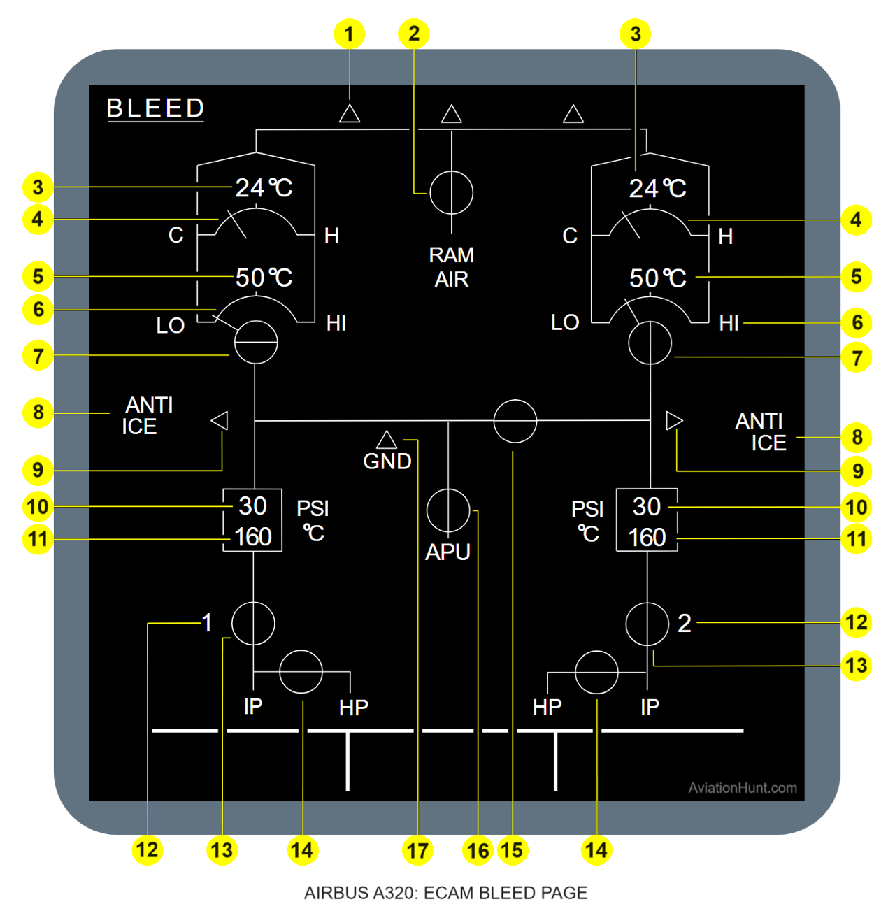
The A320 ECAM BLEED page with its parameters is described in the image above as follows:
- 1: Cold-air duct supply
- 2: Emer RAM air-valve
- 3: Pack outlet temperature
- 4: Pack turbine bypass-valve
- 5: Pack compressor outlet-temperature
- 6: Pack flow
- 7: Pack flow-control valve
- 8: Wing ANTI ICE indication
- 9: Wing anti-ice valve not closed
- 10: ENG pre-cooler inlet pressure
- 11: ENG precooler outlet temperature
- 12: ENG number
- 13: ENG bleed valve
- 14: ENG HP bleed-valve
- 15: Crossbleed valve
- 16: APU bleed valve
- 17: Ground supply
Reference Aircraft: A320neo/LEAP-1A26
1. Cold air duct supply
- Indications of Bleed Users.
- The triangles indicate if the mixer unit is supplied by air from packs or ram air.
- The triangles are amber if the two flow control valves and the RAM air valve are fully closed (in flight).
- The triangles are amber if the two flow control valves are fully closed (on ground).
- They are green in the other cases.
- The same principle applies to the flow bar which links the pack to the triangles. They are amber when the relevant pack flow control valve is fully closed. They are green in the other cases.
2. Emer RAM air valve
- The valve is normally green and closed.
- Valve green and open: This is the case when the EMER RAM air valve is fully open.
- Valve amber and open: This is the case when the EMER RAM air valve is fully open and the aircraft is on ground.
- Valve amber and in transit: This is the case when the EMER RAM air valve is neither fully closed nor fully open.
- Valve amber XX: This is the case when the EMER RAM air valve status is not available from the SDAC, or the EMER RAM AIR valve is found faulty on the SDAC incoming bus (valve status fully open and fully closed at the same time). The RAM AIR links are always green, except in case 1 where the upper link is not displayed.
3. Pack outlet temperature
- The PACK outlet temperature is normally displayed in green.
- The temperature is displayed in amber when higher than 90°C.
- The temperature is replaced by amber XX when the value is not available from the SDAC. The temperature can change from -95 to 225 °C by step of 5 °C. The unit °C is always displayed in cyan.
4. Pack Turbine Bypass Valve
- The needle position shows the position of the pack turbine bypass valve. Thus, the hot air flows to control the pack discharge temperature.
- The C (cold) indication shows the minimum supply of hot air flow – pack turbine bypass-valve closed: 0%.
- The H (high) indication shows the maximum supply of hot air flow – pack turbine bypass-valve open: 100%.
- The needle is normally green.
- The needle is amber when the valve is faulty.
- If the pack turbine bypass-valve position (that the pack temperature controller supplies to the SDAC through the Air Conditioning System Controller (ACSC)) is not available, the needle goes out of view and amber crosses (XX) come into view. The arc, C, and H indications are shown in white.
5. Pack compressor outlet temperature
- The temperature is normally displayed in green.
- The temperature is displayed in amber when higher than 230°C.
- The temperature is replaced by amber XX when the value is not available from the SDAC.
- The temperature can change from -95 to 995 °C by step of 5 °C.
- The unit °C is always displayed in cyan.
6. Pack flow
- The position of the needle represents the actual rate of pack flow.
- The green needle can vary between position LO and position HI. The LO position corresponds to 80% of airflow to the air conditioning packs, HI position to 120%. When there is no flow, the needle is frozen at the position 80 %.
- The needle is amber when the pack flow control valve is fully closed. When there is no flow, the needle is set at the position corresponding to the LO limit.
- When the pack flow (or the cabin pressure, or the cabin altitude) is not available from the SDAC, the needle is replaced by amber XX. The scale, the indications HI and LO are white.
7. Pack flow control valve
- Valve green and closed: This is the case when the pack flow control valve is fully closed and there is no pack valve disagree as transmitted by the SDAC.
- Valve green and open: This is the case when the valve is not fully closed and there is no pack valve disagree.
- Valve amber and open: This is the case when the valve is not fully closed and there is a pack valve disagree, transmitted by the SDAC.
- Valve amber and closed: This is the case when the valve is t fully closed and there is a pack valve disagree.
- Amber XX: This is the case when the valve position and the valve disagree status are neither available from the SDAC.
8. Wing ANTI ICE indication
- The title is displayed in white when the wing anti ice P/BSW is on.
- It is replaced by amber XX when no valid data are available from the SDAC.
- It is not displayed in all the other cases.
9. Wing anti ice valve not closed
- The triangle is displayed in green when the related wing anti ice valve is not closed and there is neither an overpressure nor an underpressure.
- The triangle is displayed in amber when:
- the aircraft is on the ground (from the landing gear status) and the related wing anti-ice valve is not closed (for 10s),
- or there is an overpressure or an underpressure.
- The triangle is not displayed when the related wing anti ice valve is closed.
- The triangle is replaced by amber XX when the related wing anti ice valve status is not available from the SDAC.
10. ENG precooler inlet pressure
- The pressure is normally displayed in green.
- It is displayed in amber when the pressure is lower than 4psi, or when there is an overpressure detected by the BMC (threshold between 57 and 60 PSI), as transmitted by the SDAC.
- It is replaced by amber XX when the pressure is not available from the SDAC.
- The pressure value can vary from 0 to 98 PSI by steps of 2 PSI.
- The unit PSI is always displayed in cyan.
11. ENG precooler outlet temperature
- The temperature is normally displayed in green.
- The temperature is displayed in amber when an over temperature (overheat) or a low temperature signal is received by the SDAC.
- Overheat: Temperature exceeds:
- 290 °C for more than 5 s, or
- 270 °C for more than 15 s, or
- 257 °C for more than 55 s.
- Low temperature is detected (only in-flight), if the bleed temperature drops below 150 °C, the wing anti-ice is on, and the pressure regulating valve is in the open position. Low temperature may, however, only be due to low outside air temperature.
- Note: When the engines are at idle, and depending on the ambient temperature, the precooler outlet temperature may be below 150 °C (displayed amber).
- The temperature is replaced by amber XX when the value is not available from the SDAC.
- The temperature can vary from 0 to 510 °C by steps of 5 °C.
- The unit °C is always displayed in cyan.
12. ENG number
- The engine number is normally displayed in white. It is displayed in amber when the DMC receives from the engine busses the signal: engine below idle.
- When this information is not available the engine number is displayed in white.
13. ENG bleed valve
- Transfer of air bleed is achieved from the IP stage of the engine HP compressor by the IP bleed check valve.
- Valve green and open: when the bleed valve is normally not fully closed as commanded (all the other following cases are not valid).
- Valve green and closed: the bleed valve is normally fully closed as commanded, for at least 5 s.
- Valve amber and closed: the bleed valve is abnormally fully closed (for at least 5 s) and there is a PRV LOW REGULATION (information supplied by the BMC to the DMC via the SDAC).
- Valve amber and open: the bleed valve is not fully closed and there is an engine pressure reg valve disagree from the BMC via the SDAC.
- XX amber: The bleed valve position (supplied by the BMC to the DMC via the SDAC) is not available.
- The IP indication is always white.
- The duct upstream of the engine bleed valve is amber when the related valve is closed and amber, otherwise it is green.
- The duct downstream of the engine bleed valve is displayed in green when the PRV is not fully closed for at least 5s and the engine is running. Otherwise, nothing is displayed.
- The ducts are not displayed when the valve status is not available from the SDAC.
14. ENG HP bleed valve
- Valve closed and green: The engine HP valve is fully closed with no HP valve fault.
- Valve open and green: The engine HP valve is not fully closed with no HP valve fault.
- Valve closed and amber: The engine HP valve is fully closed with an HP valve fault present.
- Amber xx: The valve status is not available from the SDAC.
15. XBLEED valve
- Valve open and green: when all the following cases are not valid.
- Valve closed and green: When the valve is fully closed.
- Valve closed and amber: When the valve is fully closed and there is a manual or automatic command to open, or there is a closure disagreement.
- Valve open and amber: When the valve is not fully closed and the valve status disagrees with that commanded: open (manual or automatic control) or the valve status disagrees with that commanded: closed (manual or automatic control)
- Valve in transit: When the valve is neither fully closed nor fully open.
- Amber XX: When the valve status transmitted by the SDAC is not valid or the valve status is received as faulty (fully open and fully closed at a time).
16. APU bleed valve
- Valve open and green: when all the following cases are not valid.
- Valve closed and green: When the APU bleed valve is fully closed
- Closed and amber: When the valve is fully closed for at least 10s and commanded ON (APU BLEED P/N ON).
- Amber XX: When the valve status transmitted by the SDAC is not valid.
- Not displayed: when the APU is not available.
- The title APU is displayed in white when the APU master switch is ON, or when the APU is available.
- The title is not displayed in all other cases.
17. Ground supply
- A white triangle is displayed when the A/C is on the ground.
- It is not displayed when the A/C is in flight or the information is not available.