A320 ATA 21 Technical Notes are brief and to-the-point information about the Airbus A320 Air Conditioning System, including its components and their functions. ATA Chapter 21 is titled Air Conditioning which covers the air conditioning, pressurization, and ventilation systems of aircraft.
A320 Air Conditioning System
The Airbus A320 Air Conditioning System is fully automatic. It continuously refreshes the air and maintains a selected temperature in three distinct zones: the cockpit, forward cabin, and aft cabin. Each zone’s temperature is controlled independently.
The pneumatic system supplies air through two-pack flow control valves, two packs, and a mixing unit which mixes the air that comes from the cabin and the packs. This mixed air is then distributed throughout the cockpit and cabin.
The temperature in the flight deck and cabin can be adjusted from the cockpit’s air conditioning panel. The temperature regulation is managed by the two Air Conditioning System Controllers (ACSC).
The temperature regulation is optimized through a hot air pressure regulating valve and trim air valves, which add hot air (taken upstream of the packs) to the air from the mixing unit.
A temperature control panel is also available on the Forward Attendant Panel (FAP). During flight, the cabin crew can adjust the temperature in each cabin zone (as set from the cockpit) within a range of ± 2.5 °C (± 4.5 °F).
In case of an emergency, a ram air inlet can supply outside air to the mixing unit. A ground connection supplies low-pressure air to the mixing unit.
Learn the Basics: How Does Air Conditioning Work on Airplanes?
A320 Air Conditioning Schematic
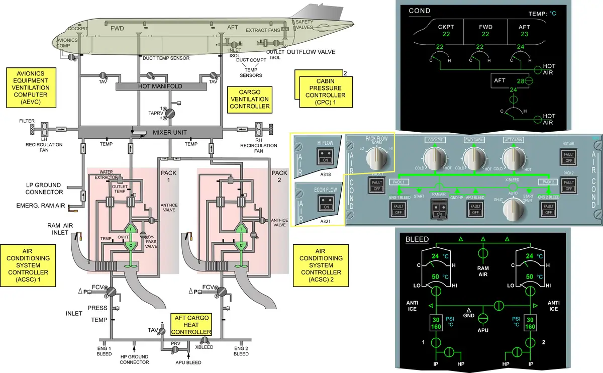
AIR CONDITIONING – TECHNICAL POINTS
- 2 Packs, 2 Recirculation fans, 2 Recirculation Filters, 1 Mixture unit
- Bleed Air > FCV > Packs > Mixture Unit > Cockpit, FWD & AFT Cabin (3 Zones).
- Recirculation fans > Mixture unit – reduces the overall bleed demand and saves fuel.
- Packs are responsible for BASIC temperature regulation.
- Pack Temp Control by modulating BYPASS VALVE & RAM-AIR INLET doors.
- Some Bleed Air (after FCV) is used for OPTIMIZED temperature regulation. This hot air is mixed with the air from mixer unit to adjust the temperature in each zone independently.
- Cabin Temp Control by using TAPRV & Trim Air Valves.
- All distributed air discharged overboard through the outflow valve to maintain pressurization.
- Computer – 2 ACSC : Compare actual temp and desired temp, then send command.
- 2 FCV – 1 for each PACK – Pneumatically-operated & electrically-controlled, by ACSC.
- Normally spring loaded to close.
- Close automatically in case of pack overheat (on ground only), engine start, or operation of the fire or ditching pushbutton.
- Ground Cooling – Low-pressure air is supplied to the mixing unit by a ground connection.
- Emergency – An Emergency Ram Air Inlet can provide ambient air to the mixing unit.
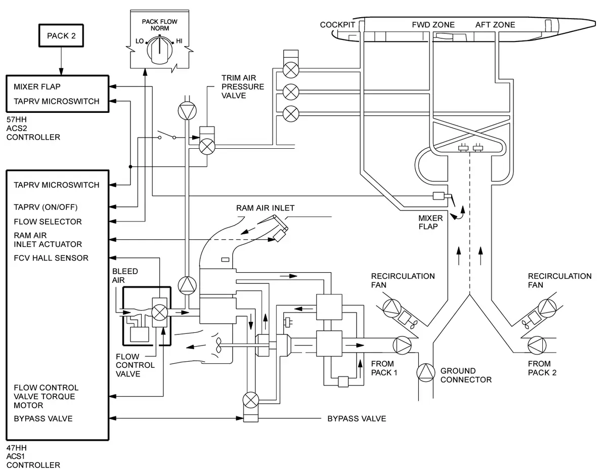
- PACK : Hot Bleed Air > FCV > Primary Heat Exchanger > Compressor of ACM > Main Heat Exchanger > Reheater > Condenser > Water Extractor > Reheater > Turbine of ACM > Condenser > Downstream Check Valve.
- Ram Air > Ram Air Inlet Door/Flap (+Actuator) > Ram Air Duct > Heat Exchanger > ACM cooling Fan > Ram Air Outlet.
- Water Extractor > Water Injector > Ram Air Duct of heat exchanger.
- Hot Air tapped from inlet of ACM compressor (after primary heat exchanger) > Bypass valve > ACM Turbine outlet.
- This modulates pack discharge temperature to the required level, if the limits for the water extractor are not exceeded.
- It is also used to stop ice formation downstream of the turbine and in the condenser.
- At ACM turbine Air expands and generates power to drive ACM Compressor and ACM Cooling Fan. The removal of energy during this process reduces air temperature, resulting in very low air temperature at turbine discharge.
- ACM Cooling Fan – Operates only on ground; Fan Plenum causes a suction for sufficient cooling on ground.
- PACK TEMP CONTROL – To control the pack outlet temperature, the ACSC modulates the BYPASS VALVE and the RAM-AIR INLET doors.
- For maximum cooling – Ram-air doors are fully open and bypass valve fully closed.
- For maximum heating – Ram-air doors are nearly closed and bypass valve fully open.
- During takeoff and landing – Ram air inlet doors will be driven to a minimum opening.
- CABIN TEMP CONTROL – 1 Hot Air Pressure Regulating Valve (TAPRV) > 3 Trim Air Valves – Controlled by ACSC.
- Mixture Flap – in the cockpit supply port of the mixer.
- BITE – Temp Control > ACSC
A320 Cabin Pressurization System
The A320 Cabin Pressurization System performs four main tasks. The ground function ensures the outflow valve is fully open when the aircraft is on the ground. During takeoff, the pre-pressurization function increases cabin pressure to avoid a surge in cabin pressure during rotation. In flight, the system adjusts the cabin altitude and rate of change to ensure passenger comfort. Finally, after landing, the depressurization function gradually releases any remaining cabin overpressure before the ground function fully opens the outflow valve again.
In case of ditching, an override switch on the control panel allows the flight crew to close the outflow valve and all valves below the flotation line.
Learn the Basics: How Does Cabin Pressurization Work on Airplanes?
PRESSURIZATION – TECHNICAL POINTS
- Pressurization system operates automatically to adjust the cabin altitude and rate of climb to ensure maximum passenger comfort and safety.
- Air Conditioning Air > Pressurized Area > discharged overboard through 1 Outflow Valve.
- Computer – 2 CPC > controls the outflow valve.
- Two automatic pressurization systems – Only one system operates at a time. Change over at each flight.
- CPC 1 and Motor 1 – System 1
- CPC 2 and Motor 2 – System 2
- One manual system – Manual Motor (incase both automatic systems fail)
- 2 Safety valves – at the rear pressure bulkhead
- To protect the fuselage against excessive cabin differential pressure.
- also protect the fuselage against negative differential pressure.
- 1 RPCU – automatically depressurizes the aircraft in case of residual pressure on ground >> fully open outflow valve through the manual motor.
- Cabin Pressure Mode Selector Switch – Automatic or Manual
- When the manual mode is selected, the Manual Vertical Speed (V/S) Control switch is used to directly control the outflow valve (indirectly, the cabin rate of climb) using the manual motor.
- The guarded DITCHING switch is used to close all lower fuselage valves so that the A/C can be sealed in the unlikely event of a ditching.
- BITE > CPC
A320 Ventilation System
The A320 Ventilation System includes ventilation for avionics, batteries, lavatories, and galleys.
The A320 Avionics Ventilation System operates automatically. It cools the electrical and electronic components located in the avionics compartment and on the flight deck. This includes the instrument and circuit breaker panels. The system utilizes two electric fans to facilitate the circulation of cooling air.
For lavatories and galleys ventilation, an extraction fan draws ambient cabin air through the lavatories and galleys and exhausts it near the outflow valve. This extraction fan runs continually when electric power is available.
For battery ventilation, a venturi in the aircraft skin draws air from the space around the batteries and vents it overboard.
NOTE: FWD & AFT Cargo – Ventilation and Heating – Both are optional systems.
A320 Avionics Ventilation Schematic
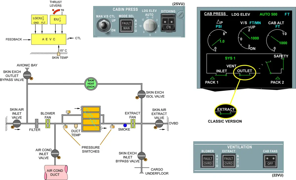
AVIONICS VENTILATION – TECHNICAL POINTS
- A blower fan and an extraction fan circulate the air through the avionics equipment.
- These fans operate continuously as long as the aircraft electrical system is supplied.
- Computer – 1 AEVC > controls the fans and configuration of the skin valves (inlet and outlet) based on flight/ground logic and fuselage skin temperature.
- 3 configurations for the skin air inlet and outlet valves –
- Open circuit: both valves are open (on ground only)
- Closed circuit: both valves are closed (in flight or low outside air temperature on ground). The air is cooled in the skin heat exchanger.
- Intermediate circuit: inlet closed, outlet partially open (small flap open).
- One small flap – in the skin air outlet valve.
- Skin Heat Exchanger is a chamber, which lets the warm air from the Avionics Equipment to be cooled down by contact of the cold fuselage skin in flight or on ground.
- Skin Heat Exchanger – Isolation Valve, Inlet Bypass v/v, Outlet bypass v/v.
- Conditioned Air Inlet Valve
- Demister Filter & Cartridge Filter
- AEVC BITE > AEVC
- Precaution – Do not use force to turn the manual handles of the skin valves. There are shear pins in the handles.
CONTROLS AND INDICATIONS
- AIR COND CONTROL PANEL
- CABIN PRESSURIZATION CONTROL PANEL
- VENTILATION CONTROL PANEL
- INDICATIONS ON ECAM COND SD PAGE
- INDICATIONS ON ECAM BLEED SD PAGE
- INDICATIONS ON ECAM CAB PRESS SD PAGE
- INDICATIONS ON ECAM DOOR/OXY SD PAGE
SENSORS
- Avionics Ventilation
- Duct Temperature Sensor – 1
- Skin Temperature Sensor – 1
- Comfort Duct Temperature Sensor – 1
- Huge temp difference – so condensation > corrosion in computers >
to prevent – This sensor delays the opening of skin valves.
- Huge temp difference – so condensation > corrosion in computers >
- Flow Control
- Differential Pressure Sensor – 2
- Pack Inlet Pressure Sensor – 2
- Pack Temp Control
- Compressor Discharge Temperature Sensor – 2
- Water Extractor Temperature Sensor – 2
- Pack Discharge Temperature Sensor – 2
- Pack Discharge Pressure Sensor – 2
- Cabin Temp Control
- Zone Temperature Sensor – 3
- Duct Temperature Sensor – 3
- Mixer Temperature Sensor – 2
COMPUTERS
- ACSC – 2
- AEVC – 1
- CPC – 2
See the location of A320 Computers.
ADDITIONAL POINTS
- PACK – Passenger Air Conditioning Kit
- Sometimes – pressurized
- In case of Sudden decomposition – safety valve will equalize pressure.
- Location of safety valve – behind galley aft bulkhead. Outlet of safety valve in THS compartment.
- Ram Air inlet door – fully closed – during take-off and landing.
- Zone temp control –
- C – 18 deg c
- M – 24 deg c
- H – 30 deg c
- CFDS – only ACSC 2
- FCV opening
- Low – 80%
- Normal – 100%
- High – 110%
- FCU
- DIP sensor – for actual outlet pressure
- PIP sensor – for inlet pressure
- FCU controlled by – Torque motor & 2 solenoid
- Normal mode
- Backup mode
- Ozone converter – are not installed in many A320F a/c.
- Hot Air for TAPRV- 4 psi higher than pack inlet pressure.
- Dew point – below dew point – water.
- Maximum cooling – at turbine.
- Compressor outlet temperature
- Important parameter – because packs deteriorate beyond this limit.
- COT Sensor
- Check in ECS report
- Range: 180 – 260 deg celcius
- 180 – FCV started closing.
- 260 – fully closed & fault light on ground. Inflight closed by pilot & ecam warnings.
- ACM seize
- Failure of any components in ACM
- Check by feeling of Hot Air by hand
- Heat Exchanger Cooling Mode – (if ACM failure/seize)
- Direct air through Bypass valve
- Can go under MEL if fault “pack overheat” is confirmed, but no pack regulation fault.
- If both packs fail – check for working of spoilers, because rapid descent will be required. Come to 10000 feet. Emergency Ram Air Inlet Flap opens only below 10000 feet. Ditching should not be selected. Delta pressure below 1 psi.
- Manual motor feedback – only through CPC1.
- CPC mode of operation
- Automatic – CPC automatically selects landing elevation – data from ADIRU.
- Semi automatic – manually select landing elevation.
- Manual – if both CPC failed.
- From base departure – blower can’t go under mel, otherwise swap with extract.
- FCV indication
- Open/close
- How much v/v is open
- RPCU – 90vu
- ACSC
- Temperature Regulation
- Flow control
- ACSC1 control – FCU for pack 1
- ACSC2 control – FCU for pack 2
- ACSC1 – only does the airflow control.
- ACSC 2 – CFDIU
- ACSC1 > BITE DATA > ACSC 2 > CFDIU
- Fap temp control: plus or minus 2.5 deg celsius
- Outflow Valve – double flap valve
- Cabin pressure
- 8000 feet – delta pressure 8.06 psi
- 9550 feet – MC
- 11300 feet – Pax Sine
- 15000 feet – outflow v/v close via motor #3, command by safety device (pressure switch)
- Safety device – is the pressure switch in each electronic actuator.
- Safety valve – 2 qty
- Above a/c flotation line
- Poppet type pneumatic valve
- In manual mode – feedback position from motor 3 is sent to CPC 1
- RPCU only when
- L/g compress
- Prk brk ON
- Master switch OFF / speed below 100 knot
- Outflow Valve not fully open
- Both CPC fail
- Avionics ventilation
- Open – ground – both fully open – more than 12 degree
- Close – inflight/ground – both fully closed
- Ground – Less than 9 degree
- Flight – Less than 32 degree
- Intermediate – more than 35 degree celsius
- Inlet – close
- Outlet – partially open (small flap open)
A320 ATA 21 SUB-CHAPTERS
- Air Distribution and Recirculation
- Lavatory/Galley Ventilation
- Avionics Equipment Ventilation
- Cargo Compartment Ventilation
- Cargo Compartment Heating
- Pressurization Control
- Flow Control
- Air Cooling System
- Emergency Ram Air Inlet
- Temperature Control
- Pack Temperature Control
- Cabin Temperature Control
- Conditioned Service Air System (CSAS)