A320 ECAM CAB PRESS PAGE
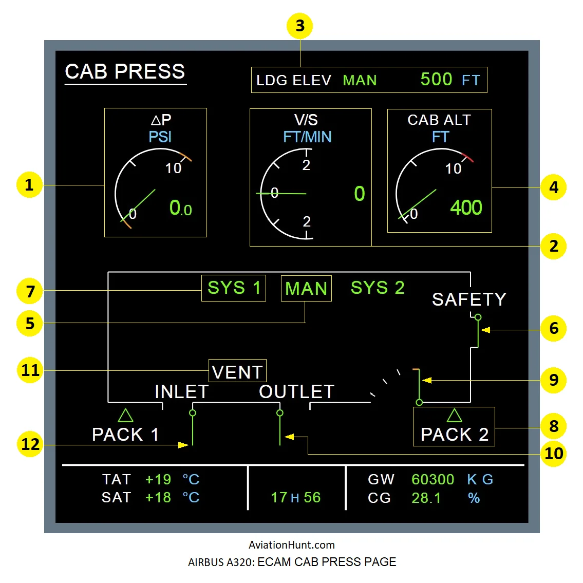
The A320 ECAM CAB PRESS page with its parameters is described in the image above as follows:
- 1: Cabin differential pressure (ΔP indication)
- 2: Cabin vertical speed
- 3: Landing field elevation indication
- 4: Cabin altitude
- 5: Mode MAN Indication
- 6: Safety Valves indication
- 7: Active System Indication SYS 1(2)
- 8: PACK 1(2) indication and Flow control indications from the packs (triangles)
- 9: Outflow valves indications
- 10: Extract Valve indication
- 11: VENT Indication
- 12: INLET Valve indication
Reference Aircraft: A320neo/LEAP-1A26
1. CABIN DIFFERENTIAL PRESSURE
- The needle and delta P digital value are normally green.
- It flashes if ΔP is more than 1.5 PSI and stops flashing when the value drops below 1 PSI.
- They become amber when out of normal range: ΔP ≤ –0.4 PSI or ΔP ≥ 8.5 PSI
- If delta P is not available the digital value is replaced by amber XX the needle goes out of view.
2. CABIN VERTICAL SPEED
- The needle and V/S digital value are normally green.
- It flashes when the cabin vertical speed reaches 1750 ft/min and stops flashing when returning below 1650 ft/min.
- If V/S is not available the digital value is replaced by amber XX the needle goes out of view.
3. LANDING ELEVATION
- LDG ELEV AUTO appears in green when the LDG ELEV selector is in AUTO.
- LDG ELEV MAN appears in green when the LDG ELEV selector is not in AUTO.
- Neither appears when the landing field elevation data from the CPC via the SDAC is not valid.
- The value 500 FT (for example) is displayed in green when landing elevation selected either automatically by the FMGS or manually by the flight crew (but not when the MODE SEL pb-sw is in MAN).
4. CABIN ALTITUDE
- The analog and digital presentations appear in green, in normal range.
- They appear in red if the cabin altitude goes above 9550 ft.
- The digital presentation pulses if the cabin altitude is at or above 8800 ft (resets at 8600 ft).
5. Mode MAN Indication
- MAN is displayed in green when the manual mode is engaged on the CABIN PRESS/MODE pushbutton switch, as transmitted by the SDAC.
6. SAFETY VALVE Position
- SAFETY white and valve green: When both safety valves are fully closed.
- SAFETY and valve amber: When at least one of the safety valves is not fully closed.
- SAFETY white and XX amber: When position of both safety valves is not available.
- Note: The safety valve opens when the indicated ΔP is between 8.9 and 9.7 PSI. The range is due to the reduced accuracy of ΔP measurements (in MAN mode), combined with the decrease in ΔP that occurs immediately after the safety valves open.
7. Active System Indication
- SYS 1 or SYS 2 appears in green when active and in amber when faulty. When either system is inactive, its title does not appear.
- Amber XX is displayed when SYS 1(2) failure or control indication is not valid from SDAC.
8. PACK Indication
- Triangle green and PACK 1(2) white: When the associated flow control valve is not fully closed (information from the SDAC).
- Triangle and PACK 1(2) amber: When the associated flow control valve is fully closed and the engine core speed is at idle or above.
- Triangle replaced by amber XX and PACK 1(2) white: When the flow control valve position is not available.
9. OUTFLOW VALVE Position
- The needle of the outflow valve is normally green.
- It becomes amber if the outflow valve opening is more than 95% and the A/C is in flight.
- The needle goes out of view and is replaced by amber XX if the outflow valve position is not available.
10. EXTRACT VALVE Indication
- Valve green and closed: When the valve is normally fully closed.
- Valve amber and closed: When the valve is abnormally fully closed.
- Valve green and open: When the valve is normally fully open.
- Valve amber and open: When the valve is abnormally fully open.
- Valve partially open and green: When the valve is normally partially open.
- Valve partially open and amber, the two conditions may apply:
- When the valve status is found neither fully open nor fully closed nor partially open.
- When the valve is found partially open and this status disagrees with that selected: the command is not in the partially open position.
- Valve replaced by XX amber: When the valve position is not available.
Also when the received status for the valve is inconsistent (status fully closed and fully open at the same time), or when none of the three valve status: fully closed, fully open, partially open, is received during a too long time (20s).
11. VENT Indication
The VENT message normally appears in white. It becomes amber, if there is a BLOWER FAULT, EXTRACT FAULT, or AVNCS SYS FAULT. BLOWER message appears in amber if there is a BLOWER FAULT. EXTRACT message appears in amber if there is an EXTRACT FAULT.
12. INLET VALVE Indication
- Valve closed and green, when all the other following cases are not valid.
- Valve open and green, when the air inlet valve is normally fully open
- Valve open and amber, when the valve is abnormally open in flight.
- Valve partially open and amber, when the valve is neither in the status fully open nor fully closed.
- XX amber, when the valve status is not available.