A320 ECAM ENGINE WARNING DISPLAY
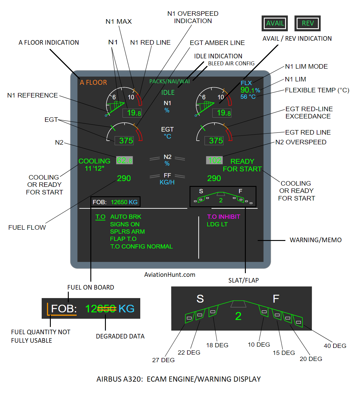
Reference a/c: A320neo/LEAP-1A26
The upper ECAM display is called ENGINE/WARNING DISPLAY, which is dedicated to providing the following information:
1. Primary Engine Parameters
N1, N2, EGT, FF
N1 INDICATION
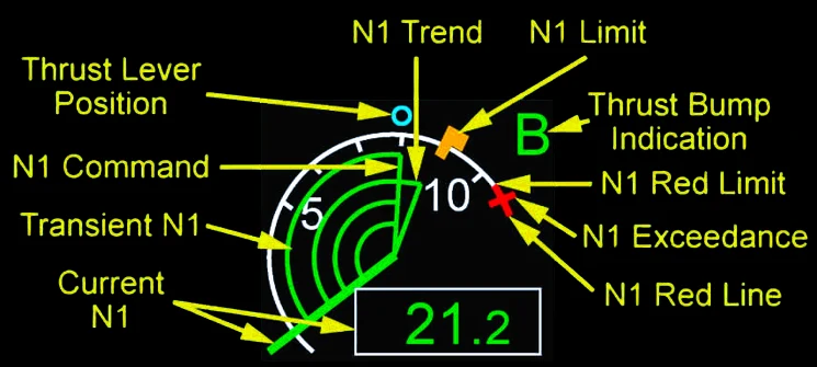
- The N1 indication is displayed in analog and digital form.
- 100% correspond to 5000 RPM.
- CURRENT N1
- Green: The current N1 is in the normal range.
- Amber: The current N1 exceeds the N1 limit. N1 actual exceeds the N1 MAX + 1% during more than 5 seconds.
- Red: The current N1 exceeds the N1 red limit. The N1 red limit is 101%. N1 actually exceeds the N1 red line by +0.1%.
- Dashed: Two amber dashes appear over the last digit when the accuracy of the N1 measurement is degraded. In case of failure of the normal N1 measurement system from the FWC, the EEC computes a theoretical value taking into account the other engine parameters. In this case, the last digit of N1 is dashed with two horizontal amber lines.
- N1 MAX
- The N1 MAX value is displayed in analog form by means of a thick amber mark across the N1 scale. It is the N1 LIMIT value corresponding to the full forward position of the throttle control lever.
- N1 TREND
- The green triangle indicates the direction of the N1 trend when the A/THR mode is active. It disappears when the N1 value has reached the N1 CMD value. It is displayed only if the engine is running.
- N1 COMMAND
- Indicates the N1 target, when the A/THR mode is active.
- The N1 CMD is displayed in analog form by means of four green arcs of a circle joining the N1 actual needle to the N1 command needle. It is displayed only with the A/THR engaged, the N1 CMD value valid, and the engine running.
- TRANSIENT N1
- The four green arcs indicate the difference between the N1 command and the current N1 when the A/THR is active.
- N1 REFERENCE (N1 throttle) – THRUST LEVER POSITION
- The small cyan circle indicates the position of the thrust lever.
- In manual mode, the blue circle corresponds to the N1 value reached after the stabilization of the engine parameters.
- N1 LIMIT
- The amber mark indicates the N1 limit. This corresponds to the maximum N1 value when the thrust levers are in the TO/GA detent.
- N1 EXCEEDANCE
- The N1 exceedance is the highest value that the N1 reached.
- The N1 exceedance appears when the current N1 exceeds the N1 red limit.
- The N1 exceedance remains even if the N1 value decreases below the N1 red limit.
- The red mark no longer appears at the next engine start sequence on the ground, or after a maintenance action.
- N1 RED LINE
- The N1 red line is represented by an arc-shaped red ribbon situated at the end of the scale.
- The N1 red line appears between the N1 red limit and the end of the scale.
- The N1 red limit is 101%.
- If the N1 actual value exceeds the N1 red line (even for a short period of time), a small red line appears across the N1 scale and then stays at the maximum value that has been reached. This indicates an N1 exceedance condition.
- Should this condition occur, the small red line disappears only after a new take-off or after a maintenance action through the MCDU. The maximum value that has been reached is stored in the BITE memory and can be read on either MCDU in the maintenance mode through the DMC menu.
THRUST RATING MODES
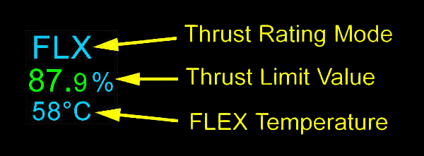
- The THRUST RATING MODES (N1 LIM MODE) is the mode in which the N1 LIMIT value is computed. Obviously, the displayed N1 limit mode is the one delivered by the EEC which is selected to display the N1 limit value.
- N1 LIMIT (THRUST LIMIT VALUE) : Indicates the N1 limit value associated with the thrust rating mode. The thrust limit value disappears when the thrust reversers are selected.
- The thrust rating modes are:
- TOGA: Takeoff or go-around thrust rating mode is selected.
- MCT: Maximum continuous thrust rating mode is selected.
- CLB: Climb thrust rating mode is selected.
- FLX: Flexible takeoff thrust rating mode is selected.
- D04: Derated takeoff (optional) thrust rating mode is selected. There are several levels of derated takeoff: D04, D08, D12, D16, D20, …
- GA SOFT: Soft go-around (optional) thrust rating mode is selected.
- MREV: Maximum reverse thrust rating mode is selected.
- These modes are selected according to the throttle control lever position (the position that is the most advanced is taken into account). Detents (mechanical notches) are associated with the mode selection.
- FLEX TEMPERATURE: Indicates the flexible temperature that the flight crew entered in the T.O panel of the FMS PERF page, when the FLX rating mode is selected, and the Static Air Temperature is at most 10°C above the flexible temperature. It is displayed in cyan color.
THRUST BUMP INDICATION
- Green: Indicates that the thrust bump is engaged.
- Amber: When on the ground, indicates that the thrust bump is selected but not engaged.
- Cyan: When on the ground, Indicates that the thrust bump is selected.
N2 INDICATION
- The N2 indications are displayed in the digital form only.
- 100% N2 corresponds to 14460 RPM.
- In a grey box: The engine start sequence or the crank process is in progress.
- Green: N2 is in the normal range.
- Red: N2 exceeds the N2 red limit. The N2 red limit is 116.5 %. A red cross appears. The red cross no longer appears at the next engine start sequence on the ground, or after a maintenance action.
- Dashed: The accuracy of the N2 measurement is degraded. Two amber dashes appear over the last digit.
EGT INDICATION
The EGT (Exhaust Gas Temperature) indication is displayed in analog and digital form.
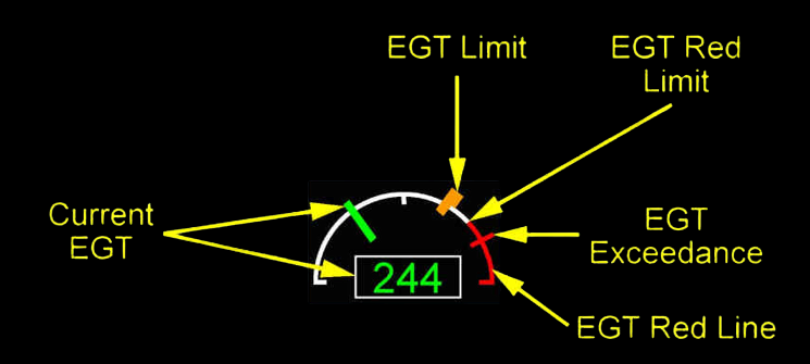
- CURRENT EGT
- Green: The current EGT is in the normal range.
- Amber: The current EGT exceeds the EGT amber limit.
- Red: The current EGT exceeds the EGT red limit.
- EGT LIMIT
- The amber line indicates the maximum EGT (i.e. the EGT limit).
- The maximum EGT is 750°C, during the engine start sequence on the ground, or 1025°C, in all other cases.
- The EGT limit does not appear: When a takeoff or a go-around mode is selected, or When the thrust reversers are selected, or If the alpha floor protection is activated.
- EGT EXCEEDANCE
- The EGT exceedance is the highest value that the EGT reached.
- The EGT exceedance appears when the current EGT exceeds the EGT red limit, or the EGT exceeds the EGT red limit.
- The red mark no longer appears at the next engine start sequence on the ground, or after a maintenance action.
- EGT RED LINE
- The EGT red line appears between the EGT red limit and the end of the scale.
- The EGT red limit is 1060°C.
FUEL FLOW
Green: The fuel flow is normal. Two values are displayed, one per engine. As for the fuel onboard information, this parameter is given in LBS.
COOLING or READY FOR START
The READY FOR START message comes into view when the N2 of the other engine is more than 50 percent, the starter air valve of the other engine is set to the closed position, the Ready-for-Start function is armed for the two engines, the master lever of the engine is set to OFF, and the aircraft is on the ground. READY FOR START message goes out of view when the master lever of the engine is set to ON, or the engine is in operation for more than 90 seconds.
The COOLING message comes into view in green when the conditions necessary to cool the engine are present, or engine cooling is in operation. The engine COOLING counter is shown below the COOLING message. The READY FOR START message has priority on the COOLING message and the COOLING counter.
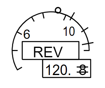
REVERSE INDICATIONS
- REV in green: On-ground, the thrust reverser system is fully deployed.
- REV in amber: The thrust reverser system is unlocked.
- In flight, the REV indication pulses for 9 seconds and then remains steady.
AVAIL INDICATION
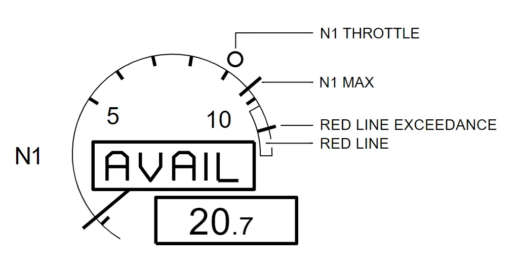
The AVAIL indication is located at the same place as the REV indication. This indicates that the engine relight is successful. The engine is started, and at or above idle. On-ground appears steady for 10 s after a successful start. In flight, pulses for 1 min after a successful relight. The AVAIL Indication disappears when the flight crew moves the thrust lever forward the idle detent.
FAILURE INFORMATION
In case of failure of any parameter, the associated indication is replaced by amber crosses. When this parameter is either N1 or EGT, the scale support is also presented in amber color.
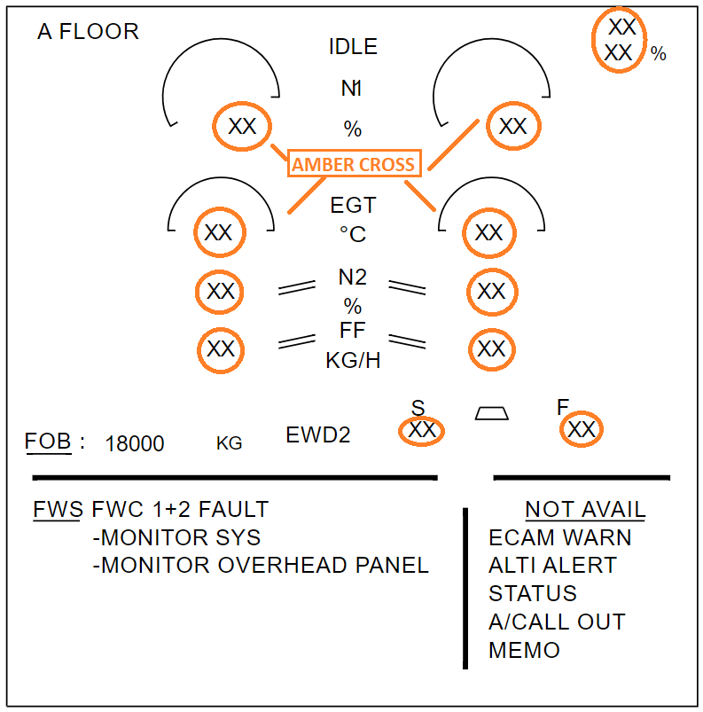
A FLOOR INDICATION
A FLOOR indication indicates the Alpha Floor protection is active. The alpha floor function is activated in case of excessive angle-of-attack and involves setting the engine thrust to TO/GA configuration. It is generated by the FAC and a signal is transmitted to the DMC for display of the A FLOOR message in amber in the upper part of the engine parameter area.
IDLE INDICATION
When both engines operate at idle, and the aircraft is in flight, the green IDLE message is displayed. The IDLE message pulses for 10 seconds and then remains steady. It is displayed only if A/THR programming is activated (transmitted by the FMGC A).
BLEED AIR CONFIGURATION
- PACKS: The engine bleeds supply the air conditioning packs.
- NAI: The engine nacelle anti-ice is on.
- WAI: The wing anti-ice is on.
- All indications can appear independently.
- They appear: On the ground when at least one engine is running; During takeoff or go-around phase, until thrust lever reduction to the CL detent; In flight, when thrust rating mode is MCT.
2. Slats and Flaps Indication
| Lever Position | Slats | FLaps | Indication |
|---|---|---|---|
| 0 | 0° | 0° | – |
| 1 | 18° | 10° | 1+F |
| 1 | 18° | 0° | 1 – after auto retraction |
| 2 | 22° | 15° | 2 |
| 3 | 22° | 20° | 3 |
| FULL | 27° | 40° | FULL |
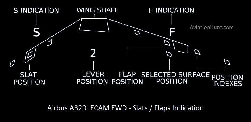
Position indexes
These white points indicate that the slats and flaps are in a selectable position. They do not
appear when the aircraft is in a clean configuration. In case of slats or flaps jamming, the dedicated index changes in color from green to amber.
F and S indication
“F” and “S” normally appear in white. They become amber, if:
- Both relevant hydraulic systems fail unless the aircraft is on the ground with both engines stopped.
- The wingtip brakes are on.
- There is a slats or flaps fault.
S-LOCKED or F-LOCKED message appears in amber, in association with an ECAM caution, when the wingtip brakes are applied, or when the system detects a non-alignment between two flaps. The “A-LOCK” legend pulses in green when the slat alpha/speedlock function is active.
Flaps/Slats actual position
These green boxes indicate the actual flaps/slats’ position. They become amber, if:
- Both relevant hydraulic systems fail unless the aircraft is on the ground with both engines stopped.
- The wingtip brakes are on.
- There is a slats or flaps fault.
Selected position
It is in blue when the surfaces are in transit. It disappears when the selected position is reached.
Flap lever position
The “0”, “1 + F”, “1”, “2”, “3”, or “FULL” legend appears.
- It is green when the slats and flaps are in the selected position. “0” is not displayed, when the aircraft attains clean configuration.
- It becomes cyan when the slats and flaps are in transit.
3. Fuel on Board Information
Fuel on board information is in KG. If the FOB (Fuel on Board) indication is displayed with two dashes across the last two digits, the FQI is in degraded mode. In this case, the ECAM FUEL page can be called on the ECAM lower display to determine which tank is affected. When the fuel quantity is not fully usable (intercell transfer valve failure or both center tank transfer valves fail in the closed position), a half amber box is displayed surrounding the FOB indication.
4. Warning and Memo Section
The lower part of the upper ECAM display provides the pilot with either warning/ caution or memo messages. The lower part is divided into 2 zones separated by a grey stripe.
Primary or independent warning messages are displayed first on the left zone, and if the number of lines of the whole text of the warning/caution messages exceeds 7, the titles of the not-shown failures are written on the right zone. The secondary failures are displayed in the right zone. Warning messages have priority over memo messages in any zone. In the case of ELEC EMER CONFIG, the secondary failures are inhibited.
- An underlined title plus framed wording indicates a primary failure.
- An underlined title plus plain wording indicates an independent fault.
- An asterisk plus a title (plain) indicates a secondary fault.
When the text of warning/caution messages exceeds the capacity of the display, a green overflow arrow appears below the grey stripe. This arrow concerns only warning messages and does not deal with memo messages. This arrow remains displayed on the screen as long as there are texts still waiting for display. The pilot can scroll down to view additional messages by pushing the CLR pushbutton on the ECAM control panel.
STS appears below the grey ribbon at the same location as the overflow arrow provided that this one is away. This message indicates to the pilot that the status page is no longer empty.
ADV appears in normal and single display configuration to signal to the pilot that a parameter drifts in an A/C system. As the corresponding system page cannot be displayed on the lower ECAM display unit, the pilot has to fetch the information on the ECAM control panel: the associated pushbutton switch flashes to indicate which system is concerned.
Memos list functions or systems that are temporarily used in normal operations. They are normally green but may be amber in abnormal situations. The memo messages can be either A/C system functions that are selected (like LDG LT) or special checklists like take-off memos or landing memos.
To improve its operational efficacy, the computer inhibits some warnings and cautions for certain
flight phases. It does so to avoid alerting the pilots unnecessarily at times when they have high workloads, such as during takeoff or landing. In these two phases, the DU displays magenta
memos: “T.O. INHIBIT” (flight phases 3, 4, and 5), and “LDG INHIBIT” (flight phases 7 and 8).