A320 ECAM ENGINE SD PAGE
Reference Aircraft: A320neo/LEAP-1A26
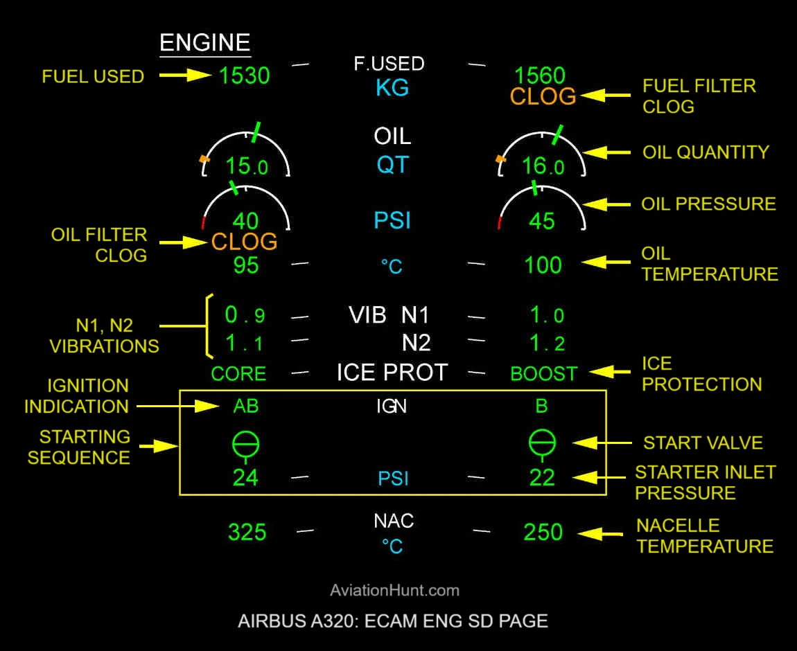
Oil Pressure Indication
- Green and steady in normal operation.
- Green pulsing (with automatic display of ENGINE page in flight phases 2 and 6):
- When the oil pressure > higher limit – 1 psi. OR
- When the oil pressure < lower limit and N2 actual > 75%.
- Pulsing stops:
- When the oil pressure < higher limit – 4 psi. OR
- When oil pressure > lower limit + 2 psi.
- Steady red if the oil pressure drops strictly below the very low-pressure limit and until it rises strictly above the very low-pressure limit + 0.5PSI.
- In case of invalidity of the oil pressure parameter, digits are replaced by amber crosses. The needle and the red arc are removed.
- The oil pressure red arc represents the very low oil pressure limit and it is displayed:
- When the very low limit oil pressure is valid, and
- When the oil pressure data is valid.
- The analog display can vary from 0 to 100 psi.
- The digital display can vary from 0 to 998 psi in 2 psi steps.
Oil Quantity Indication
- The oil quantity needle is always green.
- The digital indication of the oil quantity is green in normal operation.
- The oil quantity needle and the digital indication are green and pulsing (with the automatic display of the ENGINE page in flight phases 2 and 6):
- When the oil quantity is less than or equal to 1.2 + 0.25 quarts (low oil-quantity advisory).
- They stop pulsing: When the oil quantity is greater than or equal to 1.2 + 1.75 quarts (low oil-quantity advisory + 1.5).
- In case of invalidity of the oil quantity parameter, digits are replaced by amber crosses. The needle, the tick amber are removed.
- The analog display ranges from 0 to OILQTYMAX value.
- The oil quantity maximum value is 17.1 QT.
Fuel Used Indication
- For a given engine, the Display Management Computer (DMC) computes the fuel used from the engine start-up to its shutdown.
- The fuel used indication remains displayed after the power cut of the Electronic Control Unit (ECU).
- The fuel used indication is given in KG.
- The display can vary from 0 to 45,360 KG in 10 KG steps.
- It is normally displayed in green.
- Two amber dashes appear over all five digits. The value accuracy is degraded. This occurs when the Fuel Flow is not valid in flight, for more than 1 min.
- The fuel used is replaced by amber “XX” after a long power supply interrupt of the DMC (more than five seconds) in flight when the information is not available from the ECU bus.
N1 N2 Vibration Indication
- The N1 (N2) vibration digital value is: Green during correct operation.
- Green and pulses on the Electronic Engine Control (EEC) control if the N1 (N2) engine vibration is more than a specified threshold.
- The EEC calculates this threshold value.
- Amber if the N1 (N2) engine vibration is too high.
- The advisory level is equal to the limit that follows: Limit = 6U for N1 and 4.3U for N2.
- If the advisory level is reached, the indication is displayed in amber and the ENG 1(2) HIGH VIBRATION ECAM warning is displayed on the upper DU. If the indication is not available, the corresponding indication is replaced by two amber crosses.
- The display can change from 0 to 12.8 in increments of 0.1.
Oil Filter CLOG Indication
- No display in normal operation.
- When the pressure drop across the main supply oil filter is excessive, an amber “CLOG” is displayed.
Fuel Filter CLOG Indication
- When the pressure drop across the fuel filter is excessive for at least 5 seconds, an amber CLOG is displayed under the digital FUEL USED indication.
Starting Sequence Indications
- The starting sequence is displayed when:
- The automatic starting sequence of engine 1 is in progress, Or
- The automatic starting sequence of engine 2 is in progress, Or
- The manual starting sequence of engine 1 is in progress, Or
- The manual starting sequence of engine 2 is in progress, Or
- The aircraft is on ground and at least one engine is below idle with its ignition selected, Or
- At least one engine crank is selected.
- The indications below come into view in the starting sequence.
- Position indication of the starter shutoff valve
- Open green: When the valve is fully open.
- Closed green: When the valve is fully closed.
- Amber “XX”: When the parameter related to the position of a given starter shutoff valve is not valid at the DMC input.
- Bleed pressure
- The bleed pressure upstream of the precooler is normally green.
- It becomes amber below 21 psi with actual N2 greater than or equal to 10% and if the engine starter air valve is open or when there is an overpressure.
- If the bleed pressure value (transmitted by the Flight Warning Computer (FWC) or the System Data Acquisition Concentrator (SDAC)) is not available, it is replaced by amber “XX”.
- The display can vary from 0 to 998 psi in 2 psi steps.
- Ignition indication
- For a given engine, the indication of the selected ignitor A or B or AB is green.
- A blank is displayed when no ignitor is selected.
Nacelle Temperature
- Green and steady in normal condition.
- Green and pulsing in case of advisory triggered upon EEC information.
- In case of an advisory, an automatic SD SEN page call is performed in flight phases 2 and 6. Nacelle temperature indications are displayed for the two engines when an advisory is triggered at least on one engine.
- Amber XX is displayed in case of invalidity of the nacelle temperature parameter.
- When no advisory occurs on either engine, the title NAC and the nacelle temperatures are not displayed.
- The display can vary from -95°C to +995°C in 5°C steps.
Engine Oil Temperature
- Green and stable in normal operation. The oil temperature is in the permitted limits, or
- Amber and stable when the temperature is less than 19 degrees Celsius for two seconds. This is to tell the crew that the oil temperature is not sufficient to increase the speed of the engine for the take-off.
- If the Display Management Computer (DMC) receives from the Electronic Engine Control (EEC) a low oil temperature signal that gives an oil temperature between 17.5 degrees Celsius and 19 degrees Celsius, the oil temperature indication is amber and 20 degrees Celsius (the indication is rounded up to 20 degrees Celsius).
- If the DMC receives from the EEC an oil temperature signal that gives an oil temperature between 15.1 degrees Celsius and 17.5 degrees Celsius, the oil temperature indication is amber and 15 degrees Celsius (the indication is rounded down to 15 degrees Celsius).
- This oil temperature indication is shown in increments of five degrees Celsius.
- Green and pulsing when the oil temperature reaches the high oil temperature advisory.
- Amber (steady) if the temperature is: Higher than the very high oil temperature limit, or Above the high oil temperature advisory for more than 15 min.
- When the parameter is received as not valid by the DMC, the value is replaced by amber “XX”.
- The display can vary from -95°C to +995°C in 5°C steps.
Ice Protection Indication
- ICE PROT is displayed in steady white, under N2 white title and above NAC white title when: Booster anti ice is activated on engine 1(2). or Variable bleed valve is activated on engine 1(2).
- CORE message is displayed in steady green, when: Variable bleed valve is activated and Booster anti ice is not activated.
- BOOST message is displayed in steady green, when: Booster anti ice is activated.