The ECAM has two display units: one for the engine/warning display (E/WD) and one for the system/status display (SD).
The System Display (SD) is normally presented on the lower ECAM display unit on the center instrument panel. It provides 11 system pages showing synoptic diagrams of the aircraft systems and a status page. These pages are displayed one at a time.
The STATUS page offers an operational summary of the aircraft’s state. In addition, a CRUISE page is automatically displayed in flight.
ECAM pages can be called up at any time by pressing the pushbutton on the ECAM Control Panel to display the system pages.
SYSTEM PAGES
ENG • BLEED • PRESS • ELEC • HYD • FUEL • APU • COND • DOOR • WHEEL • F/CTL
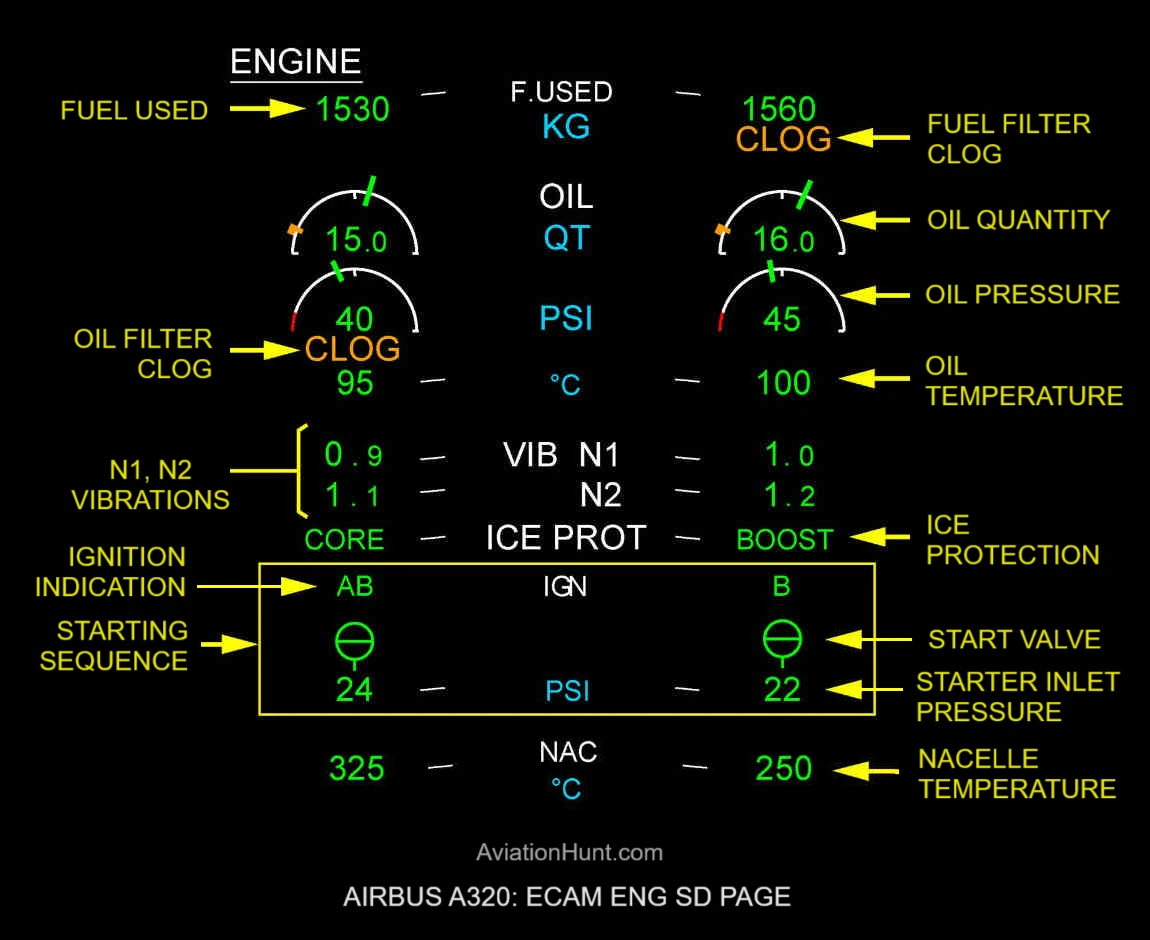
ENG
ENG (Engine) Page: Displays secondary engine parameters.
- Oil Pressure Indication
- Oil Quantity Indication
- Fuel Used Indication
- N1 N2 Vibration Indication
- Oil Filter CLOG Indication
- Fuel Filter CLOG Indication
- Starting Sequence Indications
- Nacelle Temperature
- Engine Oil Temperature
- Ice Protection Indication
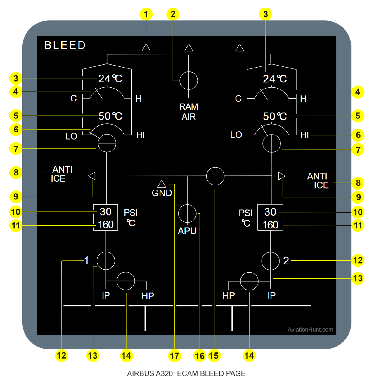
BLEED
BLEED (Air Bleed) Page: Displays the status of the air bleed system, including various valve positions and bleed air temperatures.
- 1: Cold-air duct supply
- 2: Emer RAM air-valve
- 3: Pack outlet temperature
- 4: Pack turbine bypass-valve
- 5: Pack compressor outlet-temperature
- 6: Pack flow
- 7: Pack flow-control valve
- 8: Wing ANTI ICE indication
- 9: Wing anti-ice valve not closed
- 10: ENG pre-cooler inlet pressure
- 11: ENG precooler outlet temperature
- 12: ENG number
- 13: ENG bleed valve
- 14: ENG HP bleed-valve
- 15: Crossbleed valve
- 16: APU bleed valve
- 17: Ground supply
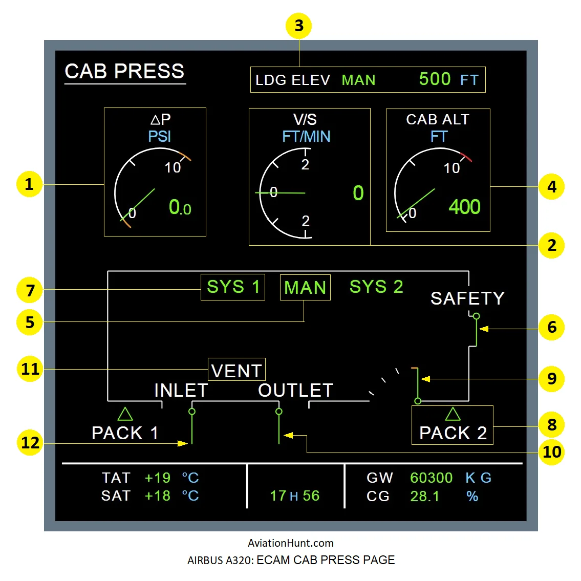
PRESS
CAB PRESS (Cabin Pressurization) Page: Displays cabin altitude, differential pressure, rate of change, and pressurization mode, as well as the status of the pressurization system valves.
- 1: Cabin differential pressure (ΔP indication)
- 2: Cabin vertical speed
- 3: Landing field elevation indication
- 4: Cabin altitude
- 5: Mode MAN Indication
- 6: Safety Valve indication
- 7: Active System Indication SYS 1(2)
- 8: PACK 1(2) indication and Flow control indications from the packs (triangles)
- 9: Outflow valves indications
- 10: Extract Valve indication
- 11: VENT Indication
- 12: INLET Valve indication
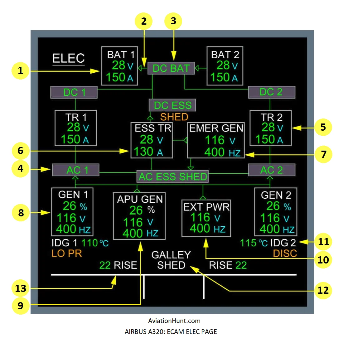
ELEC
ELEC (Electrical) Page: Displays the status of the electrical power supply, including battery voltage, generator status, and electrical load distribution.
- 1: Battery indications
- 2: Battery charge/discharge indication
- 3: DC BAT indication
- 4: Bus bar indication
- 5: TR 1(2) indication
- 6: ESS TR indication
- 7: EMER GEN indication
- 8: GEN 1(2) indications
- 9: APU GEN indications
- 10: EXT PWR indications
- 11: IDG indications
- 12: GALLEY SHED indication
- 13: RISE indication
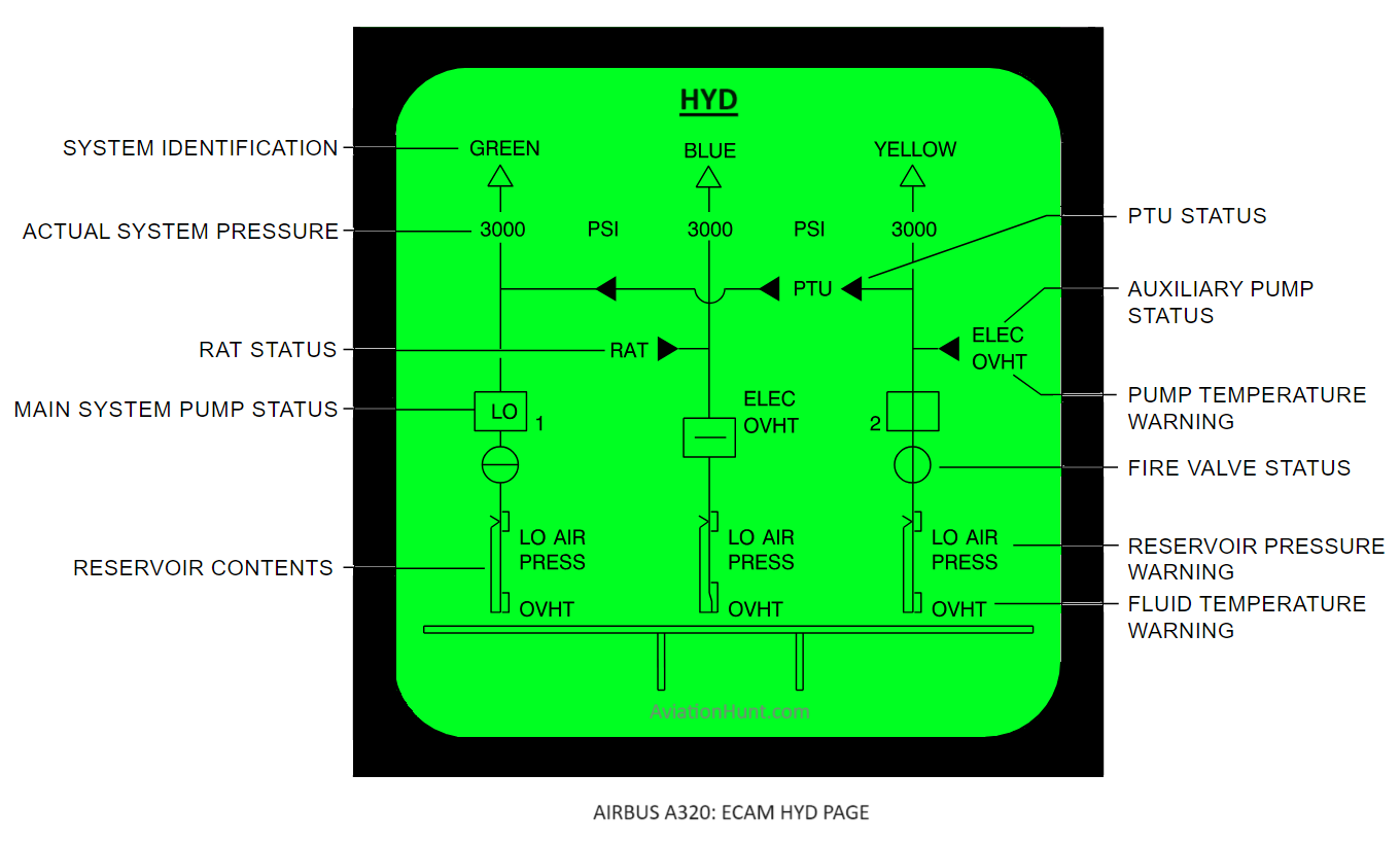
HYD
HYD (Hydraulic) Page: Displays the status of the aircraft’s hydraulic systems, including hydraulic pressure, quantity, and system configurations.
- Hydraulic system status
- Hydraulic pressure
- Yellow electrical pump
- ELEC indication
- OVHT indication
- ENG pump (Yellow / Green)
- Fire valve (Yellow / Green)
- Reservoir Level
- BLUE ELEC Pump
- RAT link to the BLUE system
- Hydraulic links
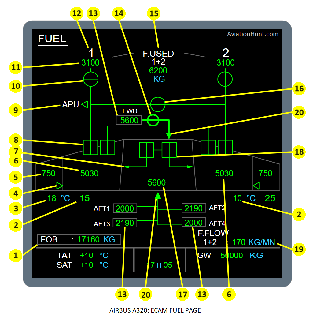
FUEL
FUEL (Fuel) Page: Displays fuel quantity and distribution in each tank, as well as fuel flow.
- 1: Fuel On Board (FOB)
- 2: Inner tank fuel temperature LH (RH)
- 3: Outer tank fuel temperature LH (RH)
- 4: Transfer valve LH (RH)
- 5: Outer tank fuel quantity LH (RH)
- 6: Inner tank fuel quantity LH (RH)
- 7: Center to inner tank transfer
- 8: Left and Right tank pumps 1 and 2
- 9: APU fuel LP valve
- 10: Engine 1 (2) fire valve (or LP valve)
- 11: Fuel used – Engine 1 (2)
- 12: Engine number
- 13: ACT fuel quantity
- 14: Forward ACT isolation valve
- 15: Total fuel used
- 16: Fuel crossfeed valve
- 17: Center tank fuel quantity
- 18: Center tank pumps
- 19: Total fuel flow
- 20: Additional Center Tank (ACT) transfer
- Fuel links
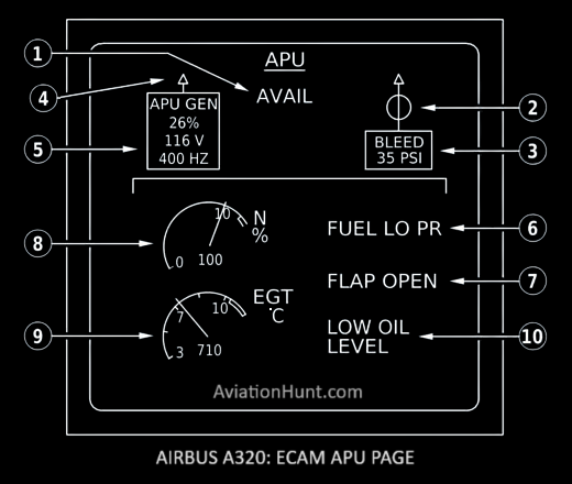
APU
APU (Auxiliary Power Unit) Page: Displays the status of the APU, including operating parameters and fault messages.
- 1: AVAIL
- 2: APU bleed air valve position
- 3: APU bleed air pressure
- 4: APU GEN line contactor indication
- 5: APU GEN parameters
- 6: FUEL LO PR
- 7: FLAP OPEN
- 8: APU N
- 9: APU EGT
- 10: LOW OIL LEVEL
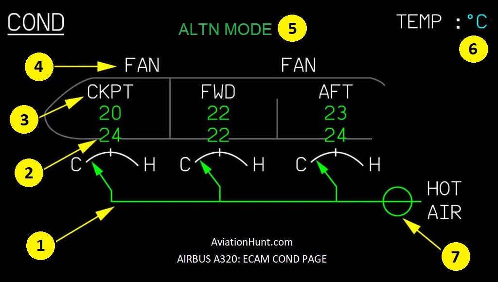
COND
COND (Air Conditioning) Page: Displays the status of the air conditioning system, including temperature and control settings.
- 1: Zone Trim Air Valve Position
- 2: Duct Temperature
- 3: Zone Temperature
- 4: Cabin Recirculation Fan Status
- 5: Pack Control Mode
- 6: TEMP Unit Indication
- 7: Hot Air Shutoff Valve
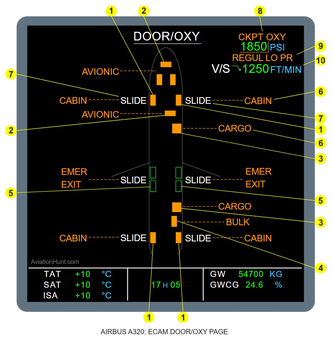
DOOR
DOOR/OXY (Doors/Oxygen) Page: Displays the status of the cabin doors and oxygen system.
- 1: Cabin Doors
- 2: Avionic Doors
- 3: Cargo Doors
- 4: BULK Cargo Door
- 5: Emergency Exit
- 6: Door Name
- 7: Slide Indication
- 8: Crew Oxygen
- 9: REGUL LO PR Indication
- 10: Cabin V/S (displayed only in flight)
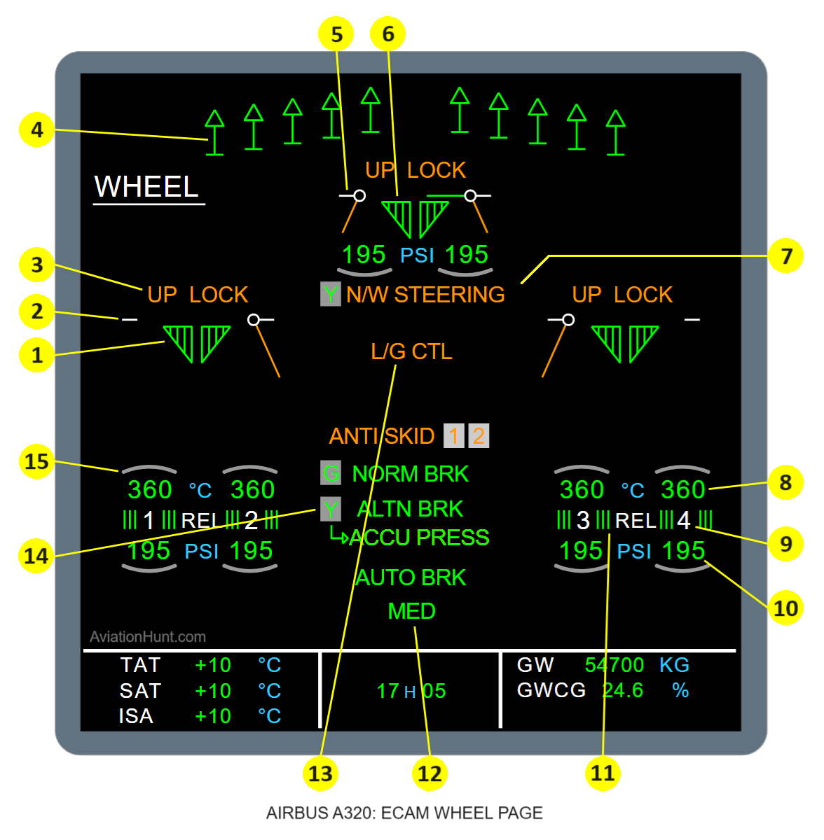
WHEEL
WHEEL Page: Displays the status of the landing gear, wheels, and brakes.
- 1: L/G position
- 2: L/G door operation
- 3: UP LOCK message
- 4: Spoilers position indication
- 5: Nose L/G doors operation
- 6: Nose L/G operation
- 7: NOSE WHEEL STEERING Message
- 8: Brake temperature
- 9: Wheel number
- 10: Tire pressure indication (optional)
- 11: Brake release
- 12: Braking Messages
- 13: L/G CTL Message
- 14: Hydraulic status
- 15: Hottest brake indication
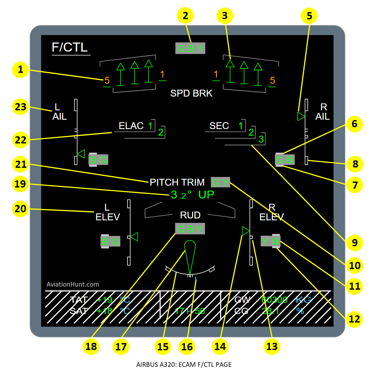
F/CTL
F/CTL (Flight Controls) Page: Displays the status of the flight control system, including control surface positions, autopilot status, and fault messages.
- 1: Spoilers status (left)
- 2: Hydraulic system pressure indication
- 3: Spoilers status (right)
- 4: FCDC Message
- 5: Aileron position
- 6: Servo control hydraulic pressure
- 7: Servo control electrical status
- 8: Aileron scale
- 9: SEC computer operation
- 10: Horizontal stabilizer hydraulic pressure
- 11: Elevator (right) hydraulic pressure
- 12: Elevator (right) electrical status
- 13: Elevator (right) scale
- 14: Elevator (right) position
- 15: Rudder scale
- 16: Rudder trim position
- 17: Rudder position
- 18: Rudder hydraulic status
- 19: Trimmable horizontal stabilizer position
- 20: Elevator (left)
- 21: Trimmable horizontal stabilizer control
- 22: ELAC operation
- 23: Aileron indication (left)