A320 ATA 31 Technical Notes are brief and to-the-point information on the Airbus A320 Indicating and Recording Systems, including its components and their functions.
A320 INDICATING/RECORDING SYSTEMS
The Airbus A320 ATA Chapter 31 covers the Indicating Systems and the Recording Systems.
Indicating Systems
- EIS : EFIS + ECAM
- Electrical Clock
- CFDS
Recording Systems
- DFDRS
- AIDS
- Printer
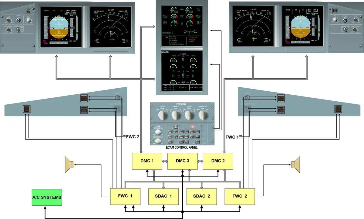
ELECTRONIC INSTRUMENT SYSTEM (EIS)
- EIS = EFIS + ECAM
- EIS Display – 6 Liquid Crystal Display – 6″ X 6″ full color, all interchangeable.
- EFIS DUs – 4 – Flight guidance and navigation information
- ECAM DUs – 2 – Aircraft monitoring
Electronic Flight Instrument System (EFIS)
- 2 PFD
- 2 ND
- 2 EFIS control section on FCU
- 3 DMC
- Switching panel for EIS reconfiguration purpose
- ATT HDG – for IR data, if IR part of ADIRS fails.
- AIR DATA – for AIR data, if ADR part of ADIRS fails.
- EIS DMC – for DMC 3 transfer.
- ECAM/ND XFR – for transferring ECAM on ND.
- Display unit brightness and ON/OFF control
- PFD/ND XFR pushbutton
- >> PFD
- FMA
- >> ND MODE
- ROSE modes 3 – ROSE-ILS, ROSE-VOR, ROSE-NAV
- ARC mode
- PLAN mode
Electronic Centralized Aircraft Monitor (ECAM) System
- 1 Upper display unit for engine/warning display (EWD)
- 1 Lower display unit for system/status display (SD)
- 1 ECAM control panel (ECP)
- 2 Flight Warning Computers (FWC)
- 2 System Data Acquisition Concentrators (SDAC)
- 3 DMCs common with EFIS
- Attention Getters – Lights & Sound
- 2 MASTER WARN (MW) lights
- 2 MASTER CAUT (MC) lights
- 2 Cockpit Audio Loudspeakers (CAL)
DU
- All 6 DUs are identical and interchangeable.
DMC
- All 3 DMCs are identical and interchangeable.
- Display Management Computers (DMCs) are data concentrators and receive data from aircraft sensors and systems. They send them to the Display Units (DUs). DUs compute and display the images on each unit.
- DMCs send data on an ARINC 629 link to the DUs.
- All 3 DMCs are common for both EFIS and ECAM functions.
- The DMCs receive data from the A/C systems, either directly or through the SDACs and FWCs.
- The DMCs receive Air Data/Inertial Reference System (ADIRS), navigation systems, Flight Management (FM), Flight Guidance and Envelope System (FGES), flight controls, engines and Flight Warning Systems (FWSs) required by the DUs in order to generate Primary Flight Display (PFD) and Navigation Display (ND) symbologies.
- The DMCs receive A/C system data on ARINC 429 buses, weather radar information on ARINC 453 high-speed bus, analog signal for the brightness control, discrete signal for the PFD/ND transfer and PFD/ND ON/OFF.
- Each DMC receives the weather radar (WXR) transceivers (XCVRs) or the Enhanced Ground Proximity Warning Computer (EGPWC) data via four ARINC 453 data buses {D1 and D2}. The DMCs retransmit the ARINC 453 bus to the EFIS DUs. As only one WXR XCVR is in operation at a time, the DMCs process information from the one in operation. The WXR enable discrete disables the operation if the plan mode is selected on the EFIS controller.
- WXR & EGPWS > DMC > EFIS DU
- WXR display is not available if PLAN mode is selected.
- When a new DMC 1, 2 or 3 is installed, the relevant software must be downloaded into it, this is done by cross loading from DMC 1, 2 or 3 via the MCDU. If a new software must be loaded, it is first done on DMC 1 from the PDL/MDDU, then a cross loading has to be performed.
- When a new DU is installed, a cross loading from the corresponding DMC has to be performed via the MCDU. The DMC BITE test is performed and the results are stored for later transfer to the Centralized Fault Display System (CFDS). It is possible to read this information via the MCDU.
- The software includes DMC (EFIS, ECAM) and DU (EFIS, ECAM) data.
- In normal operation DMC1 drives the CAPT Primary Flight Display (PFD), the CAPT Navigation Display (ND), Engine/Warning Display (EWD) and System Display (SD).
- In normal operation DMC 2 drives the F/O PFD and ND DUs.
- If DMC 1 fails, it is automatically replaced by DMC 2 for ECAM only.
- DMC 2 cannot drive the CAPT PFD and ND; a manual switching to DMC 3 is required.
- DMC 3 can drive any of the six DUs. DMC 3 is a hot spare awaiting the failure of DMC 1 or 2 and can be switched to drive the DUs linked to the failed DMC.
- PFD can be transferred to ND only, (not on EWD or SD). — Automatically.
- SD can be transferred to ND only. — manually.
- PFD or ND cannot be transferred to EWD or SD.
FWC
- The two FWCs are interchangeable.
- The FWCs compute all warnings and cautions.
- The FWCs perform three main functions:
- Data acquisition,
- Flight phase computation,
- Data warning computation corresponding to warning situations.
- Flight Warning Computers (FWCs) monitor the aircraft systems.
- Each FWC generates all warning and caution messages, supplies the attention getters, computes the flight phase and provides aural warnings.
- The DMCs preferably work with the FWC1 data. If the data is not valid or if FWC 1 is not valid, the DMCs will automatically switch to the FWC 2 Data bus.
- The RS 422 buses are used by the FWCs to send text messages (warnings, MEMO and status) to the DMCs.
SDAC
- The two SDACs are identical and interchangeable.
- The System Data Acquisition Concentrators (SDACs) receive various signals from the aircraft systems and send them to the FWCs and to the DMCs.
- All the signals (discrete, analog, digital) entering the SDACs are converted into digital format and delivered on their output buses under ARINC 429.
- Discrete signal means – Yes or No.
- The DMCs use SDAC 1 data providing it is valid. All data transfer is by ARINC 429. If the data is not valid or if SDAC 1 is not valid, the DMCs will use the data from SDAC 2.The switching is automatic.
INPUTS for EIS
- The inputs received by the FWC are used to elaborate red warnings.
- Various items of information for systems like engines, fuel, navigation and which do not agree with a warning, are directly sent to the DMCs.
- The inputs received by the SDACs are used by the DMCs to display system pages and by the FWCs to generate most of the amber warnings.
ECAM INDICATIONS
Upper ECAM >> EWD
- Single page – EWD always ON.
- Upper Area
- primary engine parameters,
- N1, N2, EGT, FF (kg/hr)
- flap/slat position indication,
- fuel on board
- primary engine parameters,
- Lower Area
- Warnings, cautions, checklist, and memos
- During takeoff and landing, most of the warnings are inhibited.
- Lower Left – Primary or Independent failures
- Lower Right – Secondary failure & Inhibited warnings.
- Additional information in some cases –
- ADV (Advisory) – if a parameter drifts from its normal value.
- STS (Status) – status message present on SD STS.
- A Green arrow (overflow) – left memo area full.
Lower ECAM >> SD
- Upper Area – displays system or status pages.
- 11 system pages
- cruise page or status page
- Lower Area – dedicated to permanent data.
- Column 1 – TAT, SAT, ISA,
- Column 2 – TIME, G LOAD,
- Column 3 – GW.
- Status page – Left & Right column
- The status page is an operational summary of the current aircraft condition. The information is displayed at the end of an ECAM procedure or upon crew request.
- Limitation, approach procedures, information and canceled cautions are displayed in the left column.
- Inoperative systems below the caption “INOP SYS” and any class 2 system failure below the caption “MAINTENANCE” are displayed in the right column.
- Overflow symbol is displayed if data overflows the left or right area.
- MAINTENANCE Message on Status – Some defects which do not trigger warnings or cautions, but which require further maintenance actions, will be indicated to the crew by means of a status indication, pulsing after engine shutdown. It is necessary to call the status page manually to see the title of the affected system.
- DEGRADED VALUE – Last 2 digits are dashed. “=” should be read as 00.
- NOT COMPUTED – 3 blues dashes replaces the values (on ground).
- DATA NOT AVAILABLE – XX amber.
ADVISORY INDICATION
- The value of some critical system parameters is monitored by an advisory mode.
- The advisory (ADV), appears by pulsing in white to indicate that an aircraft system parameter has drifted out of its normal operating range.
- The symbol ADV is displayed with pulsing in the following cases:
- When the crew has performed a manual selection for a SD page and there is an advisory on another SD page.
- When a failure has been detected by the FWC and there is an advisory on another SD.
- When there are several advisories on several SD pages. In this case, the SD page which contains the first detected advisory is displayed. However, ADV symbol will be pulsing in order to indicate to the crew that there are one or several advisories.
- In ECAM single display mode, the related page pushbutton will also flash on the ECAM Control Panel (ECP) to indicate to the crew which system page is affected by an advisory.
- ECAM Dual display mode (normal mode) means – both EWD and SD are available.
- ECAM single display mode means – only EWD are available.
STATUS INDICATION
- The status (STS) indicates that a status message is on the ECAM status page. It appears below the grey stripe at the same location as the overflow arrow provided that this one is away. This message indicates to the pilot that the status page is no more empty.
- Status (STS) indication is not shown on the EWD when the status page is displayed on the lower ECAM DU.
ARROW INDICATION
- The overflow arrow in green color indicates that warning messages exceed the capacity of the display on the left memo area.
- The overflow arrow indicates that the warning messages exceed the capacity of the display on the left memo area (7 lines). In this case, the heading titles of the warning messages are displayed on the right memo area.
ECAM WARNINGS
- Generated by FWC.
- Display on EWD lower area.
- Warnings depend on types of failures.
- There are 3 separate types of warnings or cautions:
- those associated with an independent failure,
- Failure of item of system – without affecting another one.
- eg – FWC 1 failure.
- An independent failure is displayed with the title underlined. (EWD lower LH).
- those associated with a primary failure,
- Failure of item of system – causing the loss of other equipment.
- eg – Green hydraulic system failure may lead to the loss of a pair of spoilers.
- A primary failure is displayed with a box around the failure. (EWD lower LH).
- those associated with a secondary failure.
- Loss of item of system resulting from a primary failure.
- eg – Loss of a pair of spoilers after a hydraulic system failure.
- Secondary failures are indicated on the EWD Lower Right Part – by an asterisk.
ALERT LEVEL
- Level 3 – warnings (highest priority)
- corresponds to an emergency configuration.
- Immediate corrective action.
- Continuous Repetitive Chime (CRC) or specific sound,
- Warning messages on Liquid Crystal Display (LCD),
- MASTER WARNing light flashing red.
- Level 2 – cautions
- Immediate crew awareness is required, but not immediate corrective action.
- Single Chime (SC),
- MASTER CAUTion light amber,
- Warning messages on LCD.
- The level 2 system failure has no direct consequence on flight safety.
- Level 1 – cautions
- Failures leading to a loss of redundancy or degradation of a system.
- Attention getters (lights & sounds) – not activated.
- Status messages
- Some defects which do not trigger warnings or cautions, but which require further maintenance actions, will be indicated to the crew by means of a status indication, pulsing after engine shutdown.
- Call the status page manually to see the title of the affected system.
ECAM DISPLAY WITH AIRCRAFT SYSTEM FAILURE
- In case of aircraft system failure, an aural warning, the Single Chime (SC), a visual warning and the MASTER CAUTion, attract your attention.
- The Engine/Warning Display (EWD) indicates the title of the failure and the actions to take.
- On the status and System Display (SD), the hydraulic page (for eg.) is called automatically.
- The CLeaR P/Bs come on and as long as the failure is not cleared, they stay on.
- On the hydraulic panel the FAULT lights come on, indicating the P/Bs to release out.
- The corrective actions have been taken. All the FAULT lights are off.
- On the EWD, the messages associated to the corrective action have disappeared.
CLEARING OF THE WARNINGS
- When you press CLR, on the left hand part of the EWD the title of the failure disappears and MEMO messages come back. The SD page corresponding to the first secondary failure is displayed.
- When you press CLR again, the title of the first secondary failure disappears. The system page associated with the next secondary failure is displayed.
- When you press CLR a third time, the title of the secondary failure disappears. The MEMO message comes back on the right hand part of the EWD. The STATUS page is displayed.
- STATUS REMINDER AND RECALL FUNCTION – When you press CLR a last time (means 4th time), the STATUS reminder STS on the EWD indicates that the STATUS page is not empty and the CLR P/Bs go off. On the status page, the cruise page (related to the present flight phase) comes back. The warning has been cleared. The ReCalL P/B lets the crew reactivate the Liquid Crystal Display (LCD) presentation of an alert inhibited either through the flight phase or by the CLR function.
ECAM SD PAGES
- Pages – 11 + Status/Cruise
- A page can be displayed on the SD through one of the four modes: (ECAM MODES)
Priority Order –- Normal Mode (Flight phase mode or Auto mode) – normal mode according to the flight phase is automatically presented in case of an aircraft configuration change.
- Failure mode (Warning Mode) – is automatically presented when warning/caution is triggered.
- Advisory mode – is automatically presented when a parameter is drifting.
- Manual mode – through the ECP. Note that the manual mode is cancelled in case of a warning or an advisory.
- The SD can display one of 11 system pages, cruise page or status page. In normal operation, the SD automatically shows the system pages according to the current flight phase. Nevertheless manual page selection is always possible. The CRUISE page is automatically displayed in flight (no manual selection). It displays the main system parameters to monitor during the flight. Priority is given to automatic display.
ECP ALL KEY
In the event of an ECAM control panel failure, due to the built in redundancy, the system pages are still available through the ALL key. When the ALL key is pressed and held, all the system pages are displayed successively in one second intervals. This key, when pressed repeatedly, will enable the display of the next system page.
ECAM AUTOMATIC MODE
In normal operation the ECAM system pages are displayed according to the current flight phase; this mode is called automatic mode. A flight is divided into 10 phases corresponding to an aircraft configuration change. These flight phases are generated by the FWC and used by the Display Units (DUs) to automatically call up the system pages.
- DOOR (phase 1) – The APU or engine pages are displayed in priority if the APU or the engines are started, in any flight phase. The APU page appears when APU master switch is switched ON. It disappears when APU master switch is switched OFF or the APU RPM is above 95% for 10 seconds. The ENGINE page appears at the beginning of the start sequence, and disappears 10 seconds after this start sequence.
- WHEEL (phase 2) – The WHEEL page is displayed only after the engine start has been completed, and the Engine Start switch is returned to the Normal position. The FLighT ConTroL page replaces the WHEEL page for 20 seconds when either sidestick is moved or when rudder deflection is above 22 degrees.
- ENGINE (phase 3,4,5) – During these phases, most warnings are inhibited. TO INHIBIT is displayed on the right memo area of the EWD.
- CRUISE (phase 6) – The CRUISE page appears as soon as the slats are retracted and the engines are not at take off power, provided that the landing gear is retracted. The TO INHIBIT message disappears. The CRUISE page disappears when the landing gear is selected down and ALT below 16000 ft.
- WHEEL (phase 7,8,9) – During these phases, most warnings are inhibited. “LDG INHIBIT” is displayed on the right memo area of the EWD. “LDG INHIBIT” message disappears (flight phase 9).
- DOOR (phase 10) – Five minutes after the last engine shutdown the FWC starts a new flight leg at phase 1.
EIS ABNORMAL OPERATION
DU FAILURE
If a DU fails, the flight crew may find one of the following displays:
- A blank screen with an “F” letter in amber, or
- A distorted display, or
- A blank screen with the “INVALID DISPLAY UNIT” message in amber.
- In the case of PFD failure (detected) or if the PFD unit is switched off by means of its potentiometer, the PFD is automatically displayed on the ND unit.
- The PFD/ND transfer (XFR) P/BSW provides the crew with the possibility to recover the ND image on the ND unit, if necessary.
- In the case of ND unit failure the crew has the possibility to present the ND image by pressing the PFD/ND XFR P/BSW.
- The ND screen stays instead of the PFD screen until the PFD/ND XFR P/BSW is pressed again.
- In the case of an upper display (EWD) failure or if the upper display control potentiometer is turned off, the upper display is automatically transferred on the lower display, this mode is called ECAM single display mode.
- In this case a system page can be recovered by pushing and holding a system key on the ECP or by rotating the ECAM/ND XFR selector on the switching panel in order to display the system page on the ND side.
- In case of lower DU failure or if the lower display is turned to off, no automatic reconfiguration is possible, the ECAM works in single display mode. Each crew member also has the possibility to present the SD image on the ND side only, and never on the PFD side, by rotating the ECAM/ND transfer selector switch on the switching panel.
- In case of EWD unit and SD unit failure, each crew member has the possibility to permanently present the EWD on the ND unit by rotating the ECAM/ND transfer selector switch on the switching panel.
- It is still possible to recover a system page by pushing and holding a system key on the ECP.
- In the case of PFD unit and ND unit failure (on the same side) no reconfiguration is possible.
- PFD has priority over ND. — if PFD fails, auto switch to ND.
- EWD has priority over SD. — if EWD fails, auto switch to SD.
ECP FAILURE
- If the ECP fails, the main functions, emergency cancel (EMER CANC), clear (CLR), recall (RCL), all (ALL) and status (STS) remain available.
- These are hard-wired keys.
SDAC FAILURE
- In the case of a SDAC failure, there is no operational consequence due to the redundancy of the EIS, the following message is displayed on the EWD: FWS SDAC 1 (or SDAC 2) FAULT. In case both SDACs fail the amber cautions and most of the system displays are lost. The following message is displayed on the EWD: FWS SDAC 1+2 FAULT. ENG, FUEL, F/CTL and WHEEL ECAM page data is available because it is already in ARINC 429 format and not affected by SDAC failure.
FWC FAILURE
- In the case of a FWC failure, there is no operational consequence due to the redundancy of the EIS, the following message is displayed on the EWD: FWS FWC1 FAULT or FWS FWC2 FAULT. All attention getters and loudspeakers remain operative.
- If the DMCs receive no valid data from both FWCs, the message FWS FWC1 + 2 FAULT is displayed on the EWD. All other EWD messages, aural warnings and attention getters are lost.
DMC FAILURE
- If DMC1 fails, DMC2 will automatically drive the ECAM DUs only. The CAPT has to switch to DMC3 by rotating the EIS DMC switch on the switching panel to CAPT3 in order to recover EFIS DUs also through DMC3.
- If DMC 2 fails, the F/O has to switch to DMC3 by rotating the EIS DMC switch on the switching panel to F/O 3. Either the CAPT or the F/O may select the DMC3.
EXTERNAL SOURCE INFORMATION FAILURES
- External Source Information means – ADIRS data and other a/c system data.
- In the case of external source information failures, the lost information appears in red on the PFD or ND.
- On the EWD, the failed component is also displayed. For example – NAV IR2 FAULT.
- It is possible to recover certain information by following the EWD instructions: in this example “ATT HDG SWTG F/O” on the switching panel. This enables manual source reconfiguration for attitude and heading data.
ECAM COLOR CODE
ECAM display uses a color code that indicates the importance of the failure or the indication.
- RED: The configuration or failure requires immediate action.
- AMBER: The flight crew should be aware of the configuration or failure, but need not take immediate action.
- GREEN: The item is operating normally. Information.
- WHITE: These titles and remarks guide the flight crew, as they execute various procedures.
- BLUE: These are actions to be carried out, or limitations.
- MAGENTA: These are particular messages that apply to particular pieces of equipment or situations (inhibition messages, for example).
The captions are displayed in WHITE and the units in CYAN. The values are normally displayed in GREEN.
ELECTRICAL CLOCK
- Clock is connected to hot battery bus.
- A chargeable miniature battery is inside the clock used for auto time setting.
- Provides the primary time base installed in the aircraft.
- UTC and date generation is transmitted to FMGC, FDIU and CFDIU.
- Other functions available for crew are Elapsed Time (ET) and chronometer (CHR).
- Clock can be synchronized with satellite GPS time.
- To test the clock, the annunciator light switch must be set to TEST. Then all the displays should show eight.
- CHR – if push time is pause & “:” is not shown. — (MIN : SEC)
- ET – if no colon “:” – time is pouse — (HR : MIN)
- RST is spring loaded, it returns to STP.
- UTC – HR : MIN : SEC
- INT – Internal time
- GPS – GPS time
- Both times are synchronized.
- Date can be display on same display – MO DAY YEAR
- SET – time and date – both can be set
- Ambient light sensor.
- Clock chrono – can be restarted.
- Glareshield chrono – cannot be restarted.
CENTRALIZED FAULT DISPLAY SYSTEM (CFDS)
- Centralizes and memorizes all information concerning A/C system failures.
- Controlled by a Centralized Fault Display Interface Unit (CFDIU).
- Provides a central maintenance aid which allows from the cockpit to extract the maintenance information and to initiate the tests of many systems.
Onboard Maintenance – The purpose of the onboard maintenance is to provide maintenance personnel with an aid to fault diagnosis further to a complaint of the crew.
To accomplish this goal:
- Each system includes a Built-In-Test Equipment (BITE) used for detection and isolation of faulty equipment.
- A Centralized Fault Display Interface Unit (CFDIU) acquires and processes (completes, correlates, memorizes and presents) the data transmitted by the BITEs and the warnings which have originated the crew complaint.
- The result of fault diagnosis is displayed to the maintenance operator through the Multipurpose Control and Display Units (MCDU) and the Printer which constitute the user interface.
There are two types of maintenance report:
- reports proper to the CFDIU
- reports proper to the system BITEs
CFDS is made up of the following components –
- BITEs of the systems: BITE is an electronic device (hard + soft) located inside each electrical or electronic system of the aircraft. The main functions of the BITE are to detect, locate and store the faults of the system.
- CFDIU: CFDIU is connected to the BITE of the electronic systems of the aircraft and receives the fault data from these systems. CFDIU is a computer that is used as the interface between the system BITEs and the MCDUs.
- MCDUs: used for the display of data and for sending commands to the systems.
- Printer: printer is connected to the CFDIU and serves to print reports.
- ACARS (with ATSU installed): This system is connected to the CFDIU and serves to send reports to the ground. ACARS uses VHF3.
- CDLC (Centralized Data Loading Connector): It is connected to the CFDIU and enables connection of a Portable Data Loader (PDL) for Maintenance filter database uploading.
The CFDS (BITE + CFDIU) is characterized by two operating modes : Normal Mode and Menu Mode.
System BITE Functions
- Each electrical or electronic system of the aircraft includes a fault detection, isolating and storing device called a BITE.
- All systems including a BITE system are connected to the CFDIU.
- The systems are connected to the CFDIU by means of the system bus. Exceptions : the FMGS via the FAC 1 and the EFCS via the FCDC use specific buses.
- The responsibility for fault detection and isolation lies with the system. The CFDS does not perform any processing and it does not modify the diagnosis made by the system.
- For complex systems, one of the computers plays the role of system BITE, in other words : it collects the maintenance data from the peripheral computers and it ensures the interface between the computers and the CFDS.
- The BITE enables the memorization of faults in flight and on the ground, by means of different memory zones.
- Type 1 system BITE consists of 5 zones of non-volatile memory.
- Memory for class 3 faults
- Faults detected during last flight or present flight + also faults in 63 flights
- Memory for troubleshooting data – faults in last 64 flights
- Memory for ground troubleshooting – fault detected on ground
- Memory for storing more detailed data concerning the faults – only accessible in the workshop
- Type 2 system BITE consists of 4 zones of non-volatile memory.
- Faults detected during last flight or present flight (flight memory)
- Faults detected on the ground (ground memory)
- Memory for troubleshooting data
- Memory for storing more detailed data concerning the faults – only accessible in the workshop
- Type 3 system BITEs do not have a memory.
- Type 1 system BITE consists of 5 zones of non-volatile memory.
- The faults are memorized following confirmation over several cycles (intermittent faults).
- System BITEs operate in 2 modes : NORMAL MODE and MENU MODE.
- The various fault classes detected by the system BITEs – The faults detected by the system BITEs are classified in 3 categories with respect to their consequences on aircraft safety and availability.
- Class 1 faults
- Class 2 faults
- Class 3 faults
- Various types of systems and BITE connected to the CFDS
- Type 1 systems
- Type 2 systems
- Type 3 systems
CFDIU
- The CFDIU is a computer that is used as the interface between the system BITEs and the MCDUs.
- The CFDIU permanently memorizes in real time (to within a few seconds) the maintenance messages from the system BITEs.
- The maintenance messages memorized by the CFDIU concern the internal faults detected during the current or last flight.
- The CFDIU monitors all its inputs from BITEs (monitoring of the non-refreshment of buses and the state of the discretes) and memorizes a fault message in the event of non-validity of an input.
- The CFDIU permanently memorizes in real time the ECAM warnings presented to the crew during the current or the last flight.
- The CFDIU associates the occurrence flight phase and the occurrence time (hours and minutes) with each fault memorized.
- The CFDIU associates the occurrence time (hours and minutes) and the flight phase with each warning message memorized.
- The CFDIU correlates each internal fault memorized with all external faults which may be a consequence of the internal fault.
- The CFDIU permanently monitors and memorizes the status of the systems, in other words correct or faulty operation (using fault data transmitted by the systems or the non-refreshment of inputs).
- The CFDIU establishes a fault history of the last 64 flights giving the flight counter number and the date for each flight.
- The CFDIU operates in 2 modes, Normal Mode and Menu Mode.
- CFDIU receives the flight phases and ECAM warnings from the FWC.
- The ECAM warnings are used by CFDIU to generate the LAST or CURRENT LEG ECAM REPORT. Only PRIMARY failures, INDEPENDENT failures and CLASS 2 failure messages (Maintenance status) are received.
- CFDIU is controlled from the two MCDU to display BITE data results from the system and initiate maintenance tests. The CFDIU is connected to most of the electronic systems (BITE) of the aircraft and stores failure information from these systems in memory. It also serves to initialize tests in each system.
MCDU
The MCDU consists of a screen used for the display of data, an alphanumeric keyboard and lines keys for sending commands to the systems that are connected to it:
- FMGC (Flight Management function)
- DATA LINK (ACARS) (optional)
- CFDS (Centralized Fault and Display System)
- AIDS (optional)
- SAT (SATCOM) (optional)
- ATSU (optional).
The MCDUs enable the dialog with these connected systems for the display of their data or for transmitting commands to them.
If MCDU 3 is installed (option), only MCDU 2(3) can be used for maintenance.
Reports Proper to the CFDIU
These different maintenance reports are transmitted by the CFDIU to the MCDU and they are principally intended for line maintenance.
On the ground, the menu is:
- LAST LEG REPORT
- LAST LEG ECAM REPORT
- PREVIOUS LEGS REPORT
- AVIONICS STATUS
- SYSTEM REPORT/TEST
- POST FLIGHT REPORT
- GMT/DATE INIT – only displayed in case of main clock fault
- AVIONICS CONFIG REPORT
- REPORTS PROGRAMMING – (IF ACARS MU OR ATSU INSTALLED) – ACARS MU (or ATSU) programming and printing functions programming
- PFR FILTER PROGRAM – Filter activation, Filter printing
- PASSWORD CHANGE – Password modification
In flight the menu is:
- CURRENT LEG REPORT
- CURRENT LEG ECAM REPORT
- CURRENT FLIGHT REPORT
- GMT/DATE INIT – Item added in the event of clock failure, plus long power cutoff.
- REPORTS PROGRAMMING – (IF ACARS MU OR ATSU INSTALLED) – ACARS MU (or ATSU) programming and printing functions programming
- PFR FILTER PROGRAM – Filter printing
- PASSWORD CHANGE – Password modification
Reports Proper to System BITEs Available on the MCDU
- Access to these reports is only possible on the ground.
- The reports proper to the BITE constitute the SYSTEM MENU.
- These different maintenance reports are mainly intended for maintenance at the main base.
- They depend on the type of system (1, 2, or 3) and the requirements of each system.
- Type 1 systems
- For these systems, the basic functions are:
- LAST LEG REPORT
- PREVIOUS LEGS REPORT
- LRU IDENTIFICATION
- Among the optional functions, there are:
- GROUND SCANNING
- TROUBLE SHOOTING DATA
- CLASS 3 FAULTS
- TEST
- For these systems, the basic functions are:
- Type 2 systems
- For these systems, the basic function is :
- LAST LEG REPORT
- Among the optional functions, there are:
- CLASS 3 FAULTS
- TEST
- LRU IDENTIFICATION
- For these systems, the basic function is :
- Type 3 systems
- For these systems, the only possible function is the TEST function (for the GCU emergency and DLRB/DLS) or RESET (for the 3 TRs).
CFDS Backup Modes
In the event of total CFDIU failure, it is still possible to read the maintenance information sent by certain systems by means of two test plugs located in the avionics compartment, on either side of rack 80VU.
Standby Clock Function
In normal operation, the CFDIU receives the time from the clock and synchronizes its internal clock with it. (CFDIU has its own internal clock).
In the event of fault of the main clock detected by the CFDIU (using the scrutinization of the status matrices and/or refreshment rate), the CFDIU calculates and transmits the time and the date using its internal clock. This transition does not require any reinitialization.
Reinitialization of the time and the date is only necessary after a long power cut off (> 200 ms) and it must be carried out by the crew on the MCDU through the GMT/DATE INIT function displayed by the CFDIU on the MCDU, one minute after CFDIU power-up.
CFDS FAILURE CLASSIFICATION
The various fault classes detected by the system BITEs. The faults detected by the system BITEs are classified in 3 categories with respect to their consequences on aircraft safety and availability.
CLASS 1 faults
- Class 1 failures/faults are the most serious ones and require an immediate maintenance action subject to the Minimum Equipment List (MEL).
- Class 1 faults may have an operational consequence (safety aspect) on the current flight.
- You can display the class 1 failures on the MCDU:
- in the LAST (or CURRENT) LEG REPORT.
- in the LAST (or CURRENT) LEG ECAM REPORT.
- These faults are also indicated to the crew in flight:
- by the ECAM system (upper and/or lower DU).
- by local warning in the cockpit.
- FWC receives the class 1 faults from the aircraft systems which are connected to it.
- Refer to the Minimum Equipment List (MEL): “GO”, “GO IF” or “NO GO”.
CLASS 2 faults
- Class 2 faults detected by the systems and which do not have any operational consequences (safety aspects) on the current flight or on the following flight(s) but which may have consequences if a second fault occurs.
- These faults are indicated to the cockpit crew on ground by a Maintenance STATUS on the ECAM STATUS page after the engines shut down.
- You can display the class 2 failures on the MCDU:
- in the LAST (or CURRENT) LEG REPORT.
- in the LAST (or CURRENT) LEG ECAM REPORT.
- The warning messages (class 1 and 2) presented to the crew are transmitted in real time by the FWC to CFDIU which memorizes them and constitutes the ECAM REPORT (only messages corresponding to primary and independent faults are transmitted).
- A class 2 failure has to be repaired within 10 days. Refer to the MEL: “GO” without condition.
CLASS 3 faults
- Class 3 failures have no operational consequence on aircraft safety.
- These faults are not indicated to the crew but you can display the name of the systems affected by at least a class 3 failure in the AVIONICS STATUS (only available on ground).
- Do not refer to the MEL.
- Class 3 failures have no fixed time for correction.
- However, correction is recommended to improve the dispatch reliability.
- Class 3 failures may be corrected during the A CHECK programmed maintenance operations.
CFDS AIRCRAFT SYSTEM TYPES
Various types of systems and BITE connected to the CFDS
- Type 1 systems
- can memorize failures, which occurred in the last 64 flight legs.
- Most systems are type 1 systems.
- Systems connected to CFDS with an ARINC 429 input and output bus, the input being specific to the CFDS.
- Type 2 systems
- memorize only failures from the last flight leg.
- Systems interfaced to CFDS with an ARINC 429 output and a discrete input.
- Type 3 systems
- Systems interfaced to CFDS with discrete inputs and outputs only.
- Type 3 systems are not capable of memorizing beyond the current flight.
- Type 3 system BITEs do not have a memory.
- Fault detection and transmission to the CFDIU is carried out by means of a single operating mode.
- The input discrete is used for initializing a Ground test or Reset.
CFDS REPORTS
- On ground, all the functions are available.
- In flight, only CURRENT LEG REPORT and CURRENT LEG ECAM REPORT are available.
LAST/CURRENT LEG REPORT
- internal fault messages (class 1 and 2), concerning all systems, occurred during the last or the current flight.
- the list of systems affected by this fault that are called identifiers.
- Source –
- On the ground, the item is presented under the title LAST LEG REPORT, in flight it is presented under the title CURRENT LEG REPORT.
- It can store up to 40 failures.
LAST/CURRENT LEG ECAM REPORT
- warning messages (class 1 and 2 faults) displayed on the upper ECAM display unit during the last or the current flight.
- These are the primary or independent warnings.
- On the ground, the item is presented under the title LAST LEG ECAM REPORT, in flight it is presented under the title CURRENT LEG ECAM REPORT.
- It can store up to 40 warnings.
PREVIOUS LEGS REPORT
- on the ground only, the internal fault messages (class 1 and 2) concerning all systems, appeared during the previous 64 flights (fault history). This item is the “sum” of LAST LEG REPORT items over several flights.
- At each new flight leg, the content of the LAST LEG REPORT is transferred into the PREVIOUS LEGS REPORT.
AVIONICS STATUS
- On the ground and in real time.
- Identity of systems that are affected by an internal or external fault (class 1, 2 or 3).
- (CLASS 3) is displayed next to the name of a system that is affected by at least one class 3 fault.
- To check details about CLASS 3 (or history of CLASS 3), go to SYSTEM REPORT/TEST then navigate to Particular System.
POST FLIGHT REPORT (PFR)
- a single report after the flight.
- ECAM warnings (primary and independent) and Fault Messages (class 1 and 2) of the last flight (so as to permit correlation).
- This is the “sum” of LAST LEG REPORT and LAST LEG ECAM REPORT items.
- Messages on PFR are separated into two parts :
- First part contains the ECAM warnings associated with the time, the flight phase and the ATA reference,
- Second part contains the failed LRUs associated with the time, the ATA reference and the identifiers.
- Aircraft identification, the date, the flight time, the flight number (airline) and the departure and arrival airports are included in the header.
- Programmed for automatic print after flight.
- PFR Generate –
- Beginning of PFR recording:
- if flight number inserted prior to first engine start, first engine started + 3 minutes.
- if not, aircraft speed > 80 knots.
- End of PFR recording:
- Aircraft speed < 80 knots + 30 seconds/150 seconds
- For CFDIU STD 8 and Lower – 30 seconds
- For CFDIU STD 9B – 150 seconds
CURRENT FLIGHT REPORT
- The purpose of this item is to enable manual printing or transmission through ACARS or ATSU of all current faults and warnings which occured since the beginning of the flight and up to printing and/or transmission request.
PFR/FILTER PROGRAM
- filtering all the spurious or unjustified faults/warnings.
- is to improve the operational use of the POST FLIGHT REPORT, CURRENT/LAST LEG ECAM REPORT and LAST LEG REPORT.
- Filter database is uploaded and activated.
- If YES > PFR > Database No. (DB/N)
AVIONICS CONFIGURATION REPORT
- is to present into a single report.
- all the LRU identification information sent by some type 1 & 2 BITE.
SYSTEM REPORT/TEST
- on the ground only.
- a dialog between the MCDUs and each of the systems connected to the CFDS.
- list of all the systems connected to the CFDS, in ATA chapter order.
- System menus also constitute the system BITEs. (Second Function)
LRU IDENTIFICATION – Purpose of this function is to display the computer part number.
GROUND SCANNING – Simulate flight condition to confirm faults on ground. The purpose of this function is to present the internal or external faults on the ground, whether these faults are already present in flight or not. These faults are detected through monitoring activated on manual selection of the function.
TROUBLE SHOOTING DATA – complementary information concerning the faults. Refer TSM to read this data.
TEST –
CFDS BITE (CFDIU OWN BITE)
- Power-Up Tests of the CFDIU – Integrity test of the CFDIU.
- The menu mode of the CFDIU comprises the following four functions:
- LAST LEG REPORT
- LRU IDENTIFICATION
- POWER UP TEST RESULT – Tested LRUs and related messages during CFDIU test
- GROUND SCANNING – Ground scanning of the CFDIU
- The faults of the internal components (of CFDS ) are memorized in the general LAST LEG REPORT of the CFDS and indicated in the AVIONICS STATUS.
- Internal components of CFDS
- CFDIU
- CLOCK
- MCDU 3 (if installed)
RECORDING SYSTEM
- DFDR System
- AIDS – if installed (Optional)
- Printer
FDIMS – Flight Data Interface and Management System
- FDIMS has: DFDR System and AIDS.
- FDIMS – is controlled by FDIMU.
- FDIMU has two parts – FDIU-part & DMU-part.
- FDIU-part controls DFDR System.
- DMU-part controls AIDS.
DFDR SYSTEM
Controlled by FDIU-part of FDIMU > Flight Data Interface Unit
- DFDR – Flight-parameters
- QAR – if installed (optional), same data of DFDR for quick access.
- WQAR (Wireless GroundLink QAR) includes a GSM module for data transmission. —- (optional)
- Three-axis Linear Accelerometer – Acceleration data
DFDR
- DFDR Type – SSFDR (Solid State FDR).
- DFDR is installed immediately above the CVR, in an unpressurized area of the rear fuselage.
- DFDR stores the data of the last 25 hours collected by the FDIU (Part of FDIMU).
- DFDR stores these data in a solid-state non-volatile memory which is in a crash-and-fire-protected housing.
- Underwater Locator Beacon (ULB) installed on the front face of the DFDR gives the location of the recorder if the aircraft is immersed in water following an accident.
- ULB has a battery, which is activated by both fresh and salt water.
- The operation of DFDR is automatic.
- On the center pedestal, there is a DFDR EVENT P/B, which can be used to set an event mark on the DFDR memory.
- It is possible to download recorded data on ground through the front-connector of the DFDR.
- NEO A/C – 2 Cockpit Voice Data Recorders (CVDRs).
- Cockpit Voice Data Recorder (CVDR) is a crush-survivable recorder which includes the functions of the Cockpit Voice Recorder (CVR) and the Flight Data Recorder (FDR).
- The crash-survivable housing protects the recorded medium.
- The crash-survivable housing obeys the ED-112A environmental requirements.
- CVDR has recording-time capacity minimum of 25 hours for audio and datalink, and minimum of 25 hours for flight data.
- The ULB helps to find aircraft if there was an overwater accident. It is activated when the recorder is put fully into water. A lithium-free (alkaline) non-rechargeable battery lets the signal to be transmitted for 90 day.
- The ULB sends the ultrasonic signal of 37.5 KHz when the ULB water immersion-sensor detects water.
AIDS
Controlled by DMU-part of FDIMU > Data Management Unit
- Mainly for – to monitor engine condition, APU condition and A/C performance, and
- to provide trouble shooting assistance.
- AIDS is to convert various data supplied by different aircraft systems into a recordable form. This data enables the operator to adapt his maintenance-planning.
- Digital AIDS Recorder – DAR
- Wireless Ground Link – Digital AIDS Recorder (WGL-DAR) – if installed (optional) – transmit these data through a wireless ground link to a ground station. It uses the 3G, EDGE and GPRS networks all around the world to transmit the recorded flight data.
- DMU provides an interface for PCMCIA – to upload application-software and to download AIDS-reports with a notebook-computer.
FDIMU – Flight Data Interface and Management Unit
- FDIMU can transmit reports to the Aircraft Communication Addressing and Reporting System (ACARS) and to the printer in the cockpit.
- Through the MCDUs in the cockpit, it is possible to control the FDIMU and to see system-reports. —- interface with CFDIU.
- You can load the application-software of the FDIU-part and DMU-part through a Portable Data Loader (PDL).
AIDS REPORT
- AIDS can generate system reports.
- Airbus Standard Reports are pre-programmed reports available at aircraft delivery.
- Operator can create their own reports.
- Crew can select any report to be displayed on the MCDUs.
- <06> Engine Gas Path Advisory Report – exceedance of primary engine parameters.
- e.g – EGT, N1, N2.
- <07> Engine Mechanical Advisory Report – exceedance of secondary engine parameters.
- e.g – oil pressure, oil temperature, engine vibration.
- <15> Load Report – hard landing data.
- <19> ECS Report – malfunction in the air conditioning or pressurization system.
- The parameters contained in the AIDS reports are among the parameters provided with an alpha call-up.
- Detailed parameter list associated with each report – AMM 31-37-00
- Alpha Call-Up Code
PRINTER
- Print out function.
- Automatic Print – printing function has been programmed in the corresponding system computer.
- Manual Print – MCDU initiates printing of data displayed on MCDU screen or data stored in system reports.
COMPUTERS
- SDAC – 2
- DMC – 3
- FWC – 1
- CFDIU – 1
- FDIMU – 1
- QAR – 1